
• HS Series Off-grid low frequency solar inverter 1-12KW
  • HS Series Off-grid low frequency solar inverter 1-12KW
  • HS Series Off-grid low frequency solar inverter 1-12KW
  • HS Series Off-grid low frequency solar inverter 1-12KW
  • HS Series Off-grid low frequency solar inverter 1-12KW
  • HS Series Off-grid low frequency solar inverter 1-12KW
  • HS Series Off-grid low frequency solar inverter 1-12KW
  • HS Series Off-grid low frequency solar inverter 1-12KW
  • HS Series Off-grid low frequency solar inverter 1-12KW
  • HS Series Off-grid low frequency solar inverter 1-12KW
  • HS Series Off-grid low frequency solar inverter 1-12KW
  • HS Series Off-grid low frequency solar inverter 1-12KW
  • HS Series Off-grid low frequency solar inverter 1-12KW
  • HS Series Off-grid low frequency solar inverter 1-12KW
  • HS Series Off-grid low frequency solar inverter 1-12KW
  • HS Series Off-grid low frequency solar inverter 1-12KW
  • HS Series Off-grid low frequency solar inverter 1-12KW
  • HS Series Off-grid low frequency solar inverter 1-12KW

HS Series Off-grid low frequency solar inverter 1-12KW

No.HS Series

 
Contains four functions of mains bypass, mains charging, inverterUPsfully automatic switching

  The efficiency is 3~5% higher than the ordinary power frequency series, and the self-consumptionis reduced by 30~50%
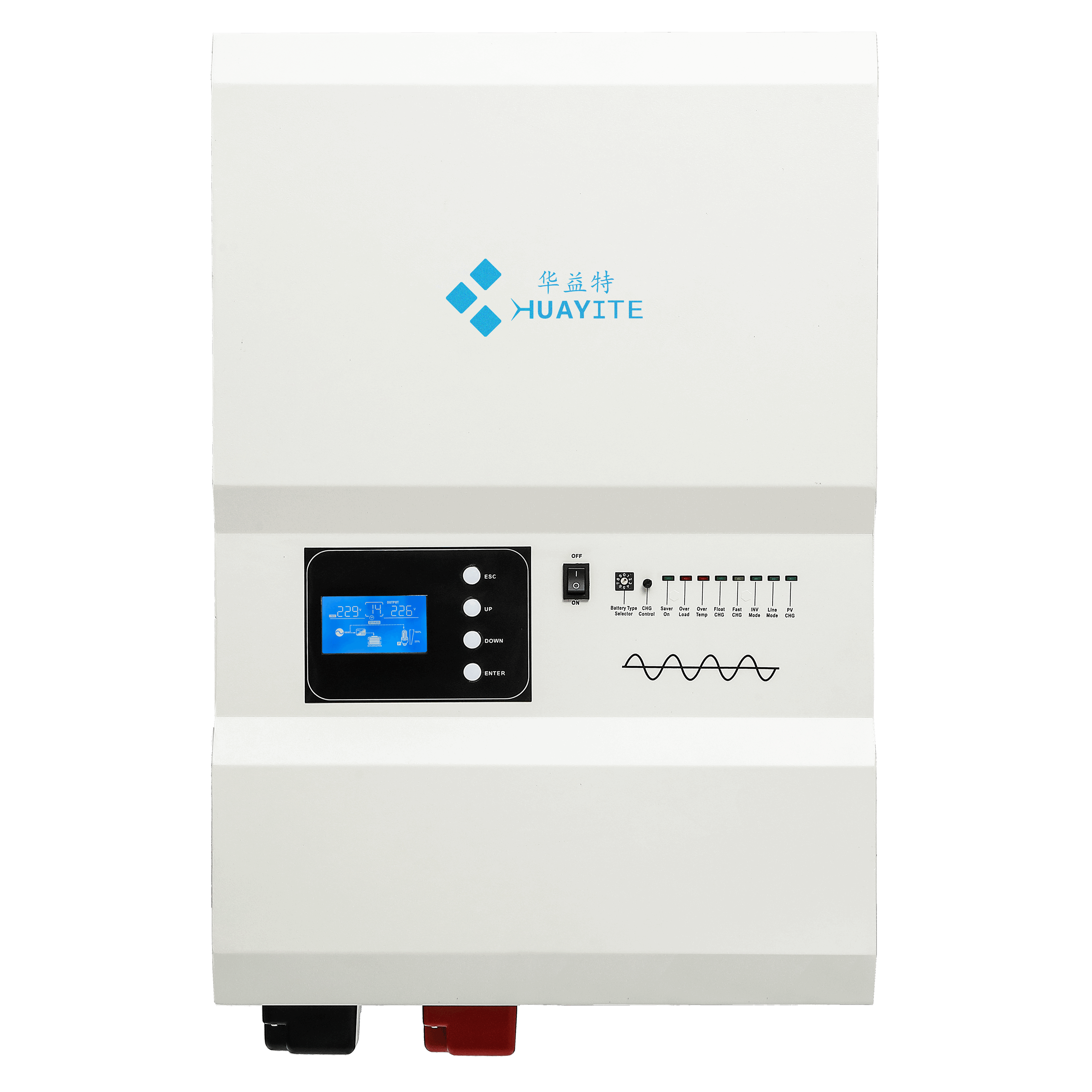
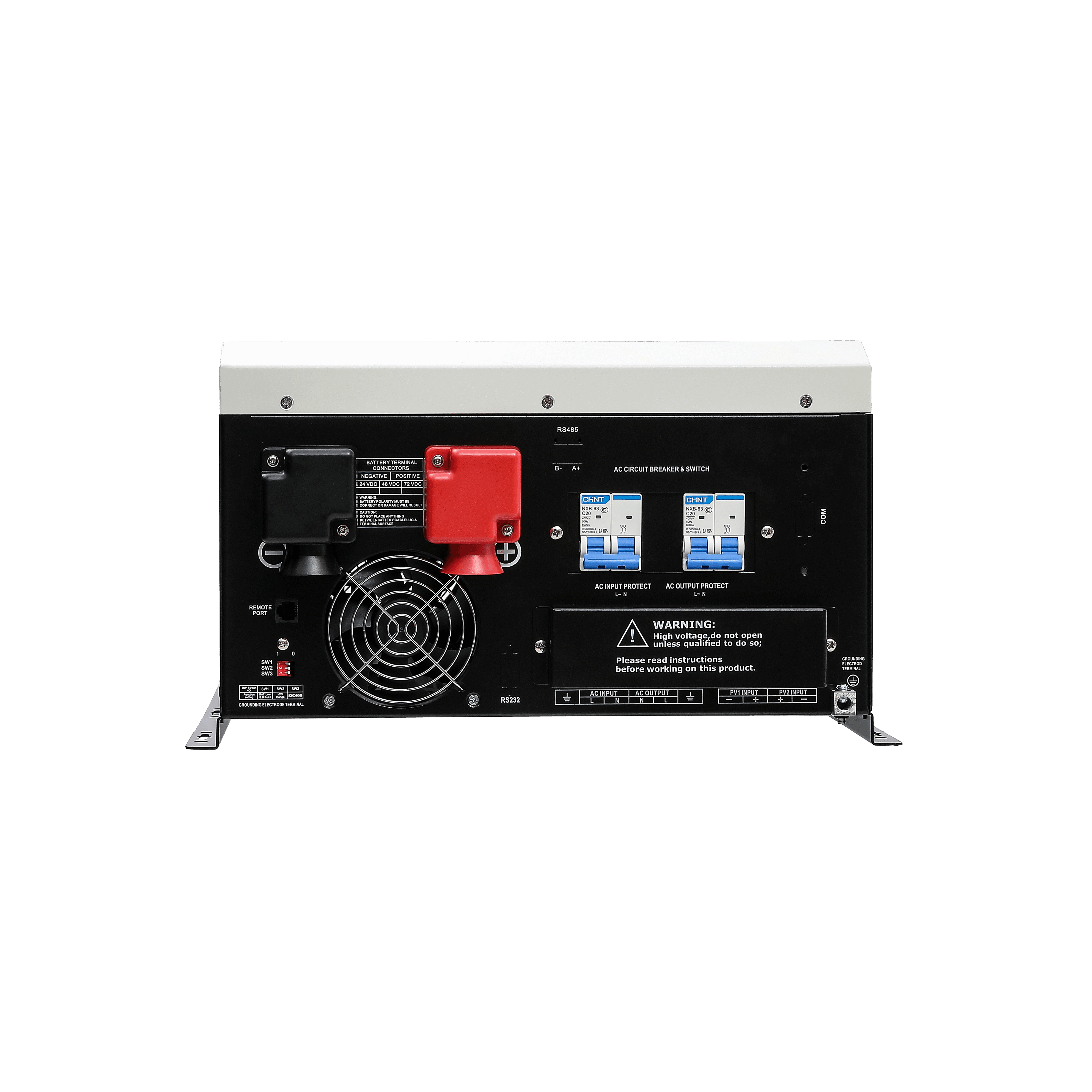
  DlP switch selection: battery undervoltage point, input AC range, energysaving mode, priority mode
  Remote communication interface R)11/Rj45/RS232/485 remote control panel (optional)
  Support PC software monitoring, support WlFl 4G module expansion to realize app cloudmonitoring (optional)
  Pure sine wave output, input and output completely isolated design
  • HS Series Off-grid low frequency solar inverter 1-12KW
  • HS Series Off-grid low frequency solar inverter 1-12KW
  • HS Series Off-grid low frequency solar inverter 1-12KW
  • HS Series Off-grid low frequency solar inverter 1-12KW
  • HS Series Off-grid low frequency solar inverter 1-12KW
  • HS Series Off-grid low frequency solar inverter 1-12KW
  • HS Series Off-grid low frequency solar inverter 1-12KW
  • HS Series Off-grid low frequency solar inverter 1-12KW
  • HS Series Off-grid low frequency solar inverter 1-12KW

Description

Product Overview

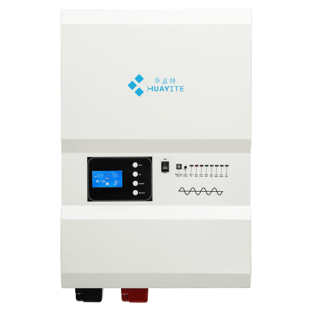
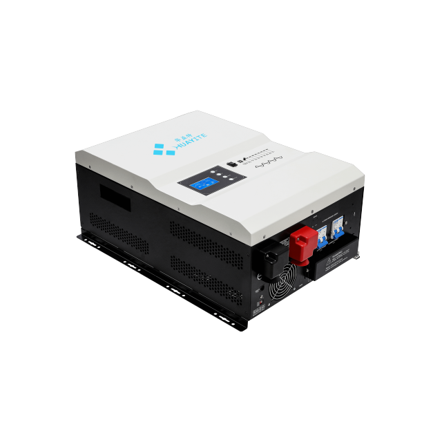
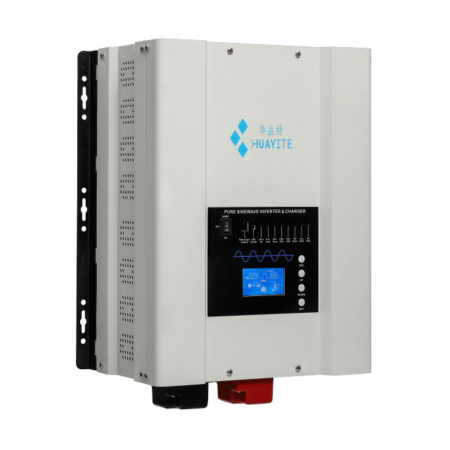
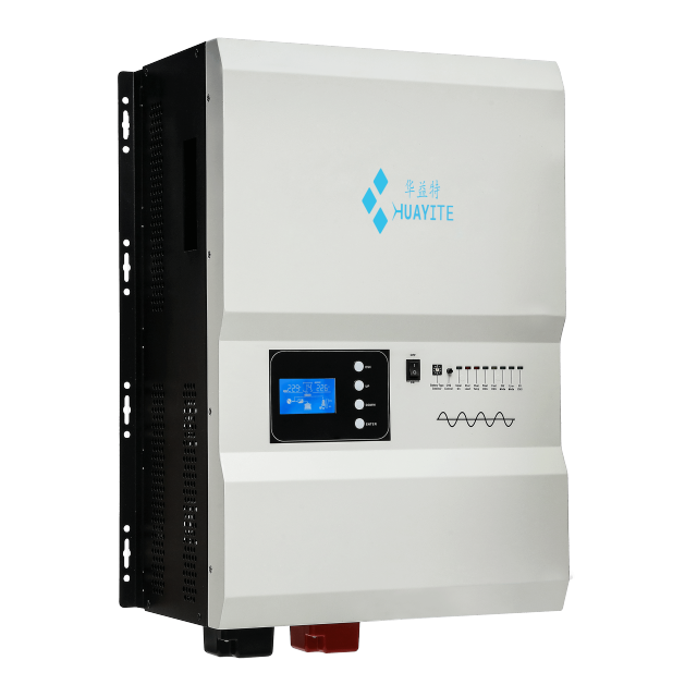
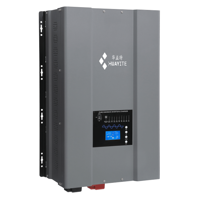
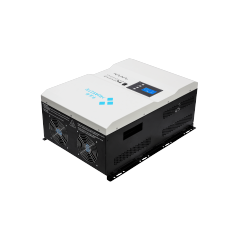
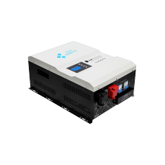
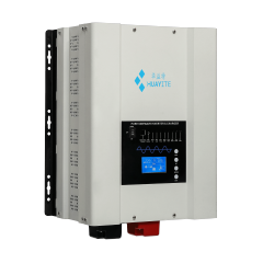
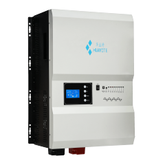
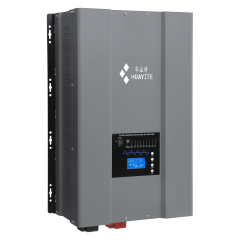
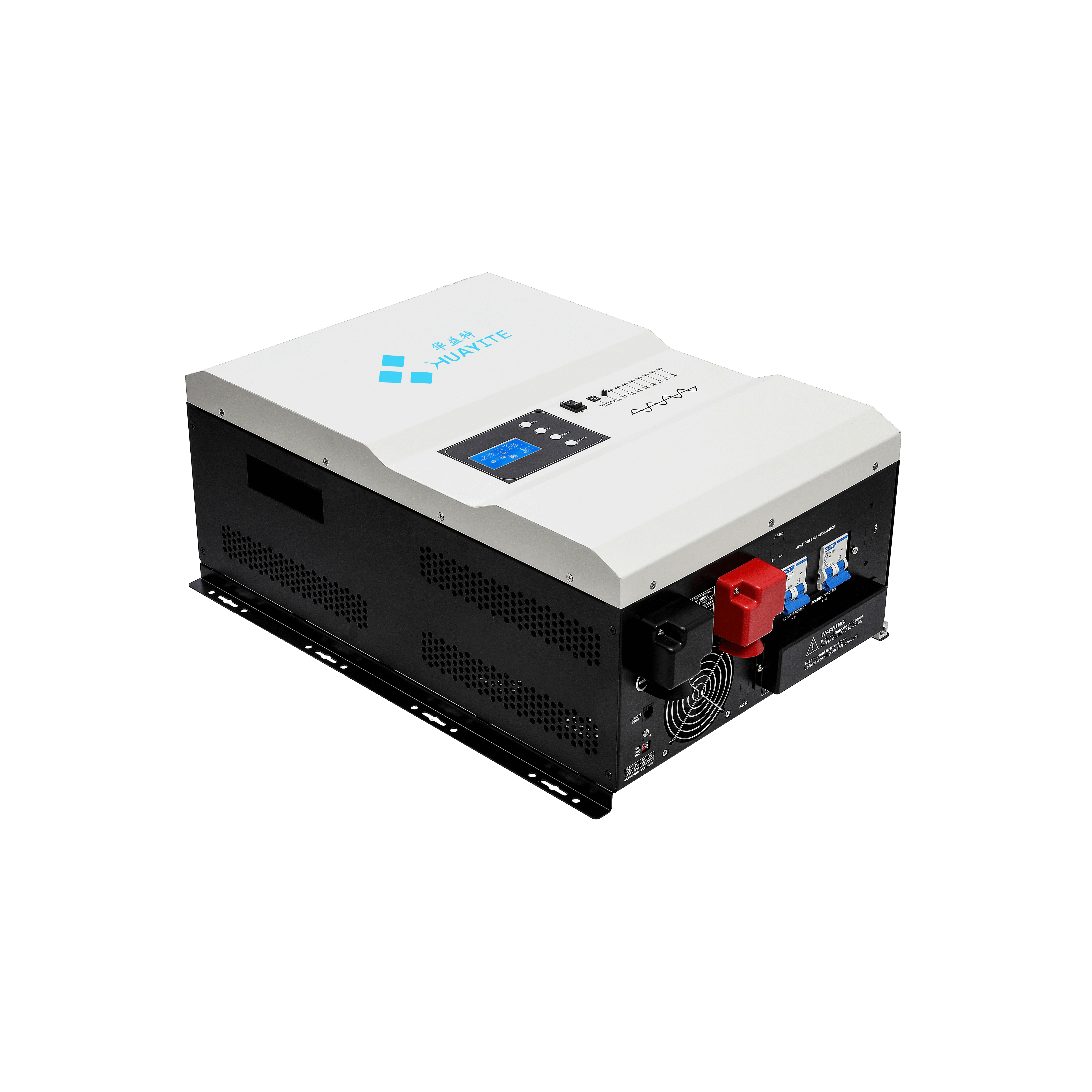
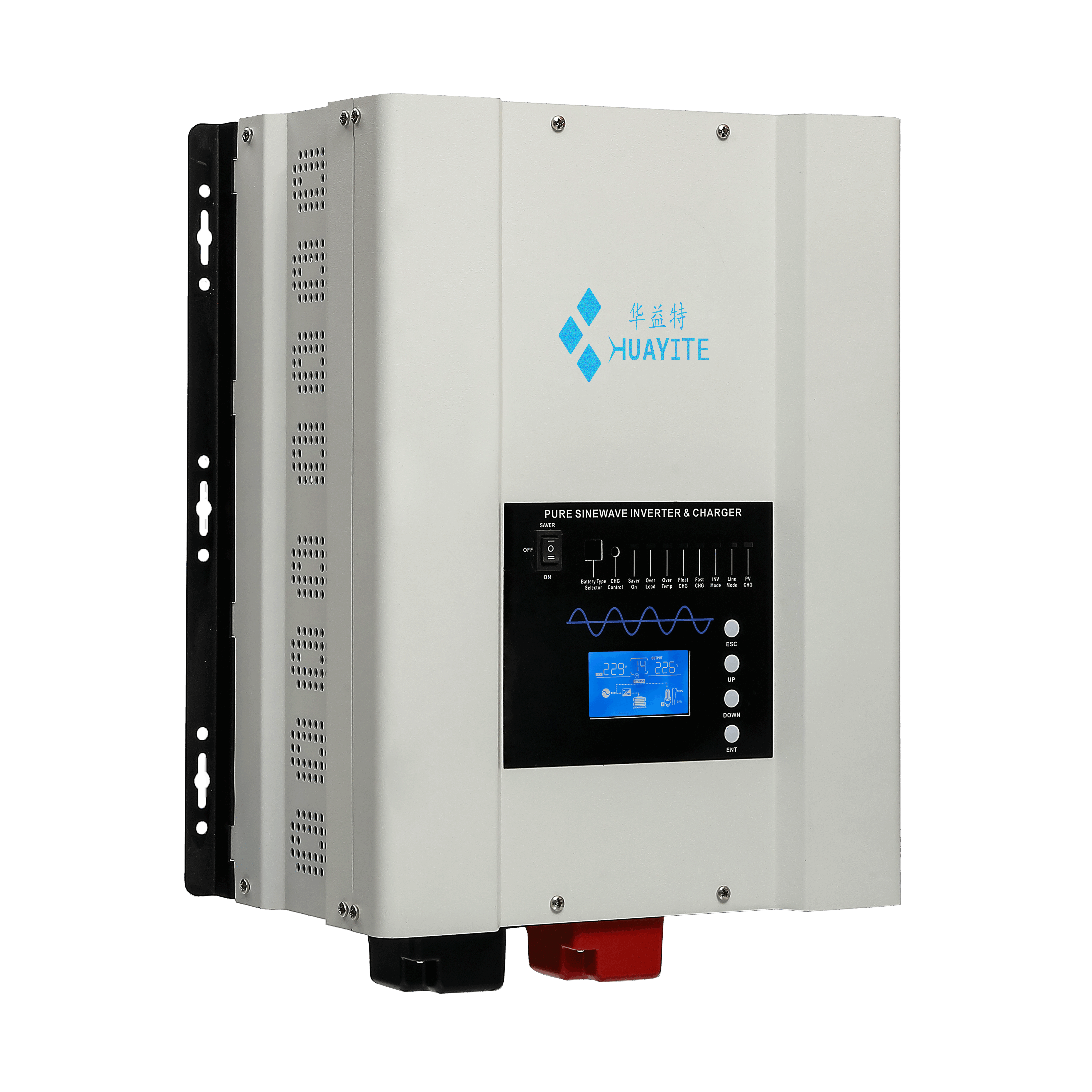
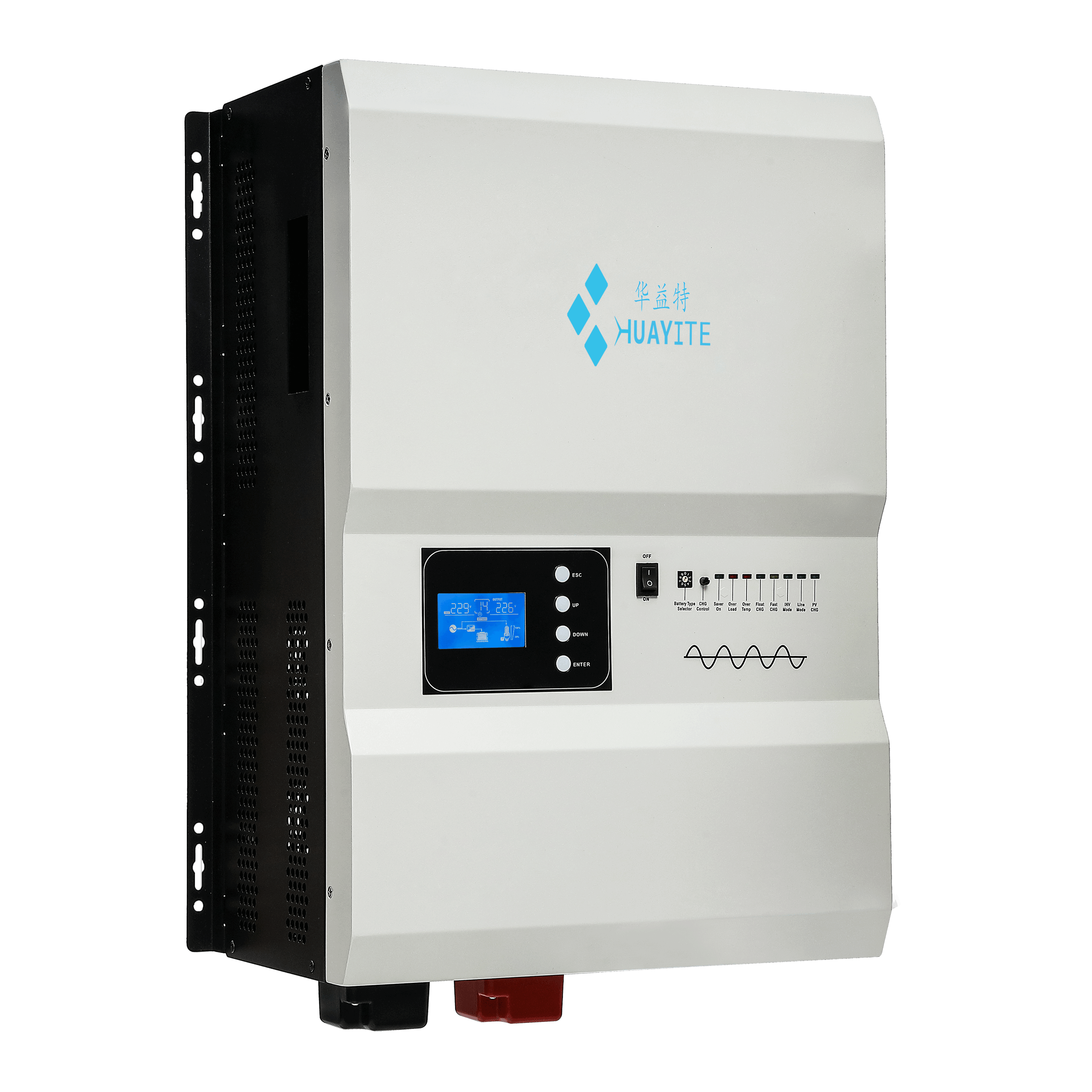
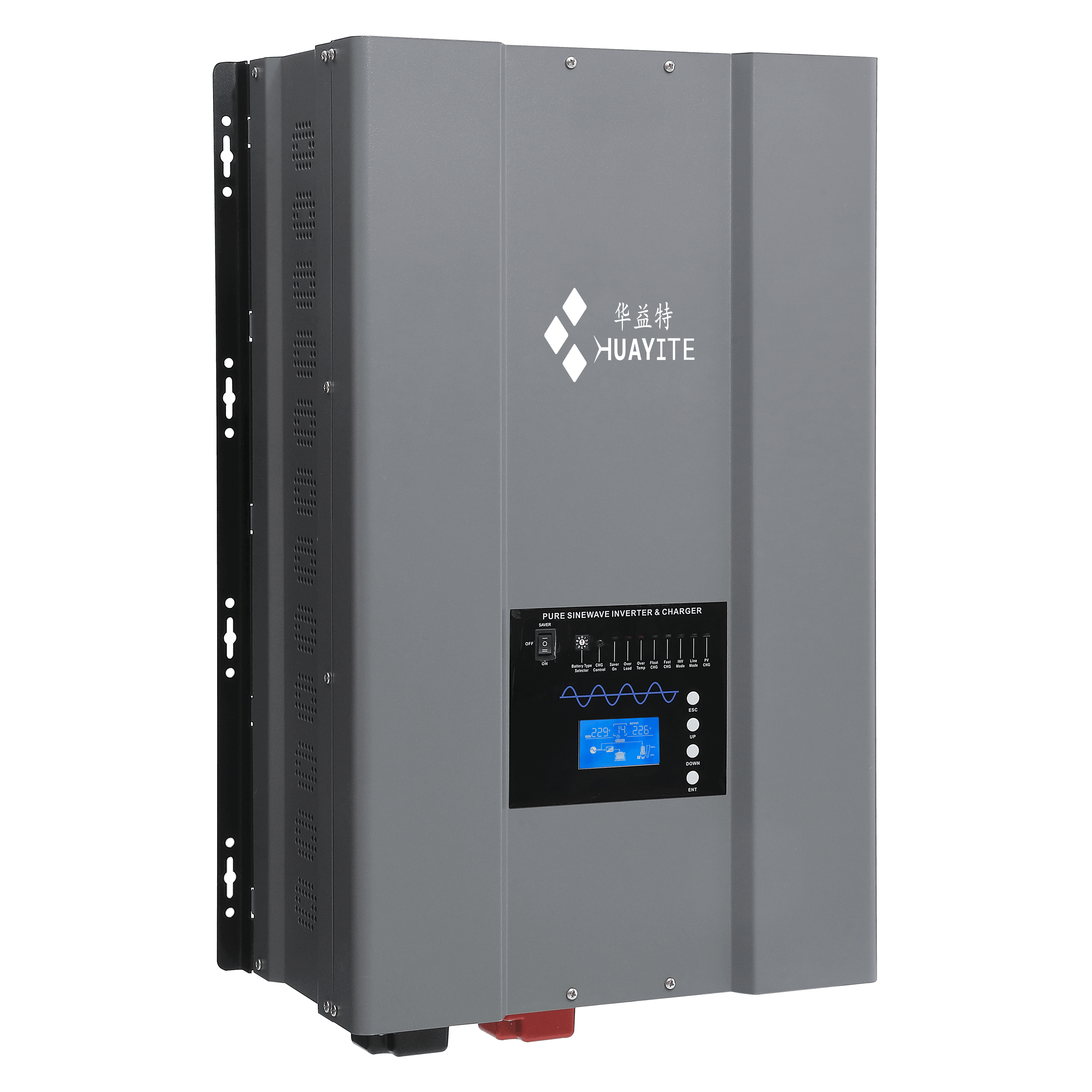
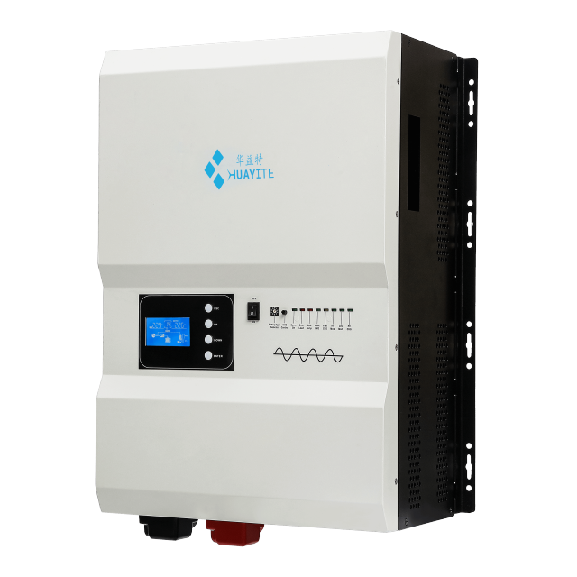
The HS Series is a solar inverter for home and commercial sites where the utility is weak, intermittent or missing altogether. Nine models cover 1kW to 12kW of continuous output, and all of them share the same low-frequency U-type transformer platform and the same four-in-one layout: mains bypass, mains charging, inverter and UPS switching inside one wall-mounted cabinet. Used as an off grid solar inverter charger, the cabinet does two jobs with one power stage. It rectifies grid or generator input to charge the battery bank, and it inverts battery DC back into AC for the load. Changeover between the two is automatic, so nobody has to stand at the panel when the mains drops. Controls, terminal layout and DIP-switch logic are shared across every rating, so an installation team learns the product once. Everything is wall mounted and fan cooled. Output is pure sine wave, the DC side is fully isolated from the AC side, and the cabinet is built to sit behind a solar array, a generator or a battery bank without extra isolation hardware. - Three times rated surge, sized for motors. Surge rating runs from 3,000VA on the 1kW model to 36,000VA on the 12kW, and each rating starts an electric motor of 1HP per kW of continuous output, so a 5kW unit takes a 5HP pump start without tripping. - One low frequency inverter platform across nine ratings. Control layout, DIP-switch settings and the manual are common from 1kW to 12kW, which keeps installer training and spare-parts stock to a single set for a whole project pipeline. - Four functions in one cabinet. Mains bypass, mains charging, inverter and UPS switching are integrated, so a separate charger and changeover panel come off the bill of materials and off the wall. - Transfer inside 10ms. Changeover is 10ms maximum, short enough for most IT, telecom and control equipment to ride through, and short-circuit protection clears a fault within one second. - Two output voltage families. Depending on the model, nominal output is 100V / 110V / 120VAC or 220V / 230V / 240VAC at ±5%, which lets one series serve markets with different distribution voltages. - Whole-system supply from one source. The MPPT charge controllers and LiFePO4 storage that sit around this inverter come from the same solar inverter manufacturer, so charge profile, voltage thresholds and protection settings are specified together rather than reconciled between separate solar inverter suppliers.
HS Series Off-grid low frequency solar inverter 1-12KW
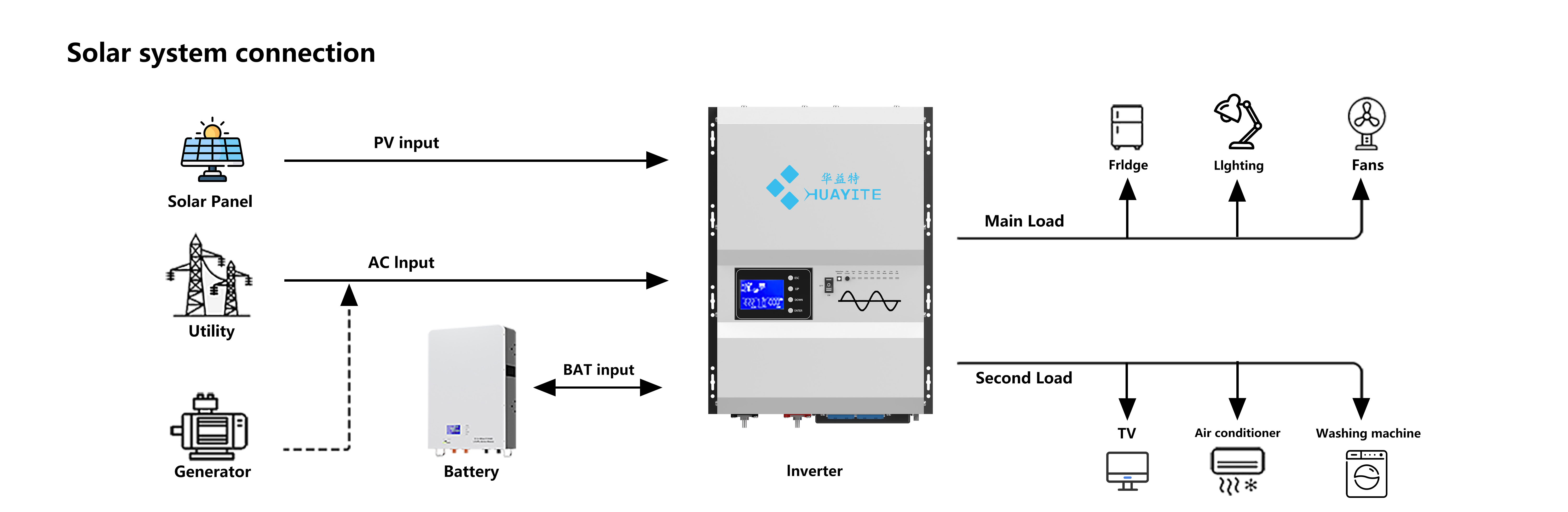
Solar inverter system connection diagram with panels, grid, generator, battery

Low-Frequency Transformer Design

At the centre of the cabinet sits a low frequency inverter stage built around a U-type transformer. The design is deliberately heavier and slower than a high-frequency switching stage: the transformer gives galvanic isolation between the DC input and the AC output, and its mass absorbs the current spikes that would otherwise reach the semiconductors.

That is what makes the unit behave as an off grid pure sine wave inverter under awkward loads. The output is a clean sine wave — or the same waveform as the supply when it is running in bypass — and a power factor range of 0.9 to 1.0 means motors, switch-mode power supplies and instrumentation can share one distribution board.

Efficiency is where the transformer earns its keep. Peak inverter efficiency is above 88% and line-mode efficiency above 95%; against an ordinary power frequency series this design runs 3-5% higher, with self-consumption reduced by 30-50%. On a site that runs around the clock, that shows up as recovered capacity in the off grid solar battery system rather than heat in the plant room. Ask us for the comparison figures for the rating you are specifying.

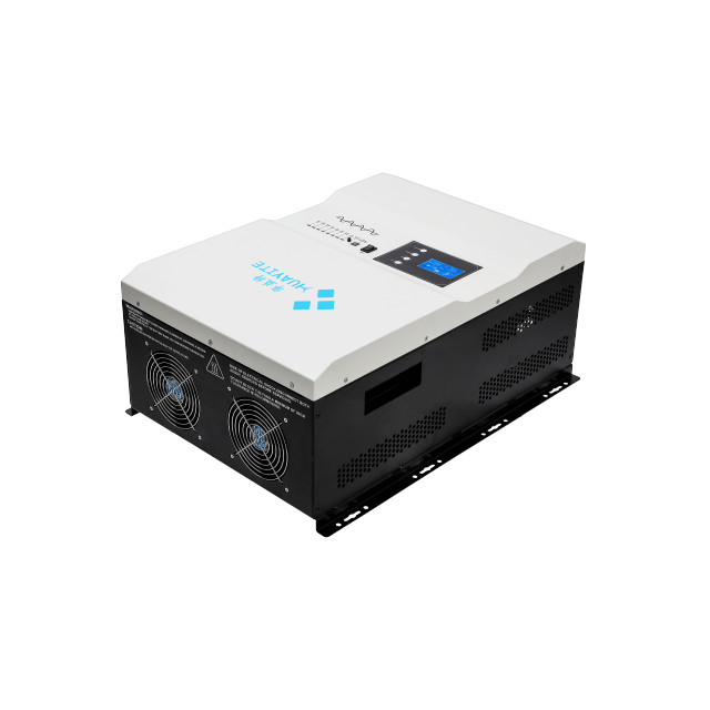
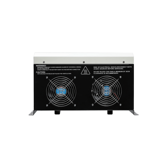
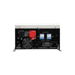
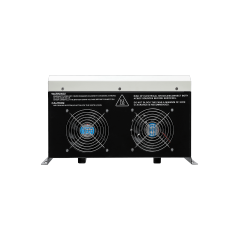
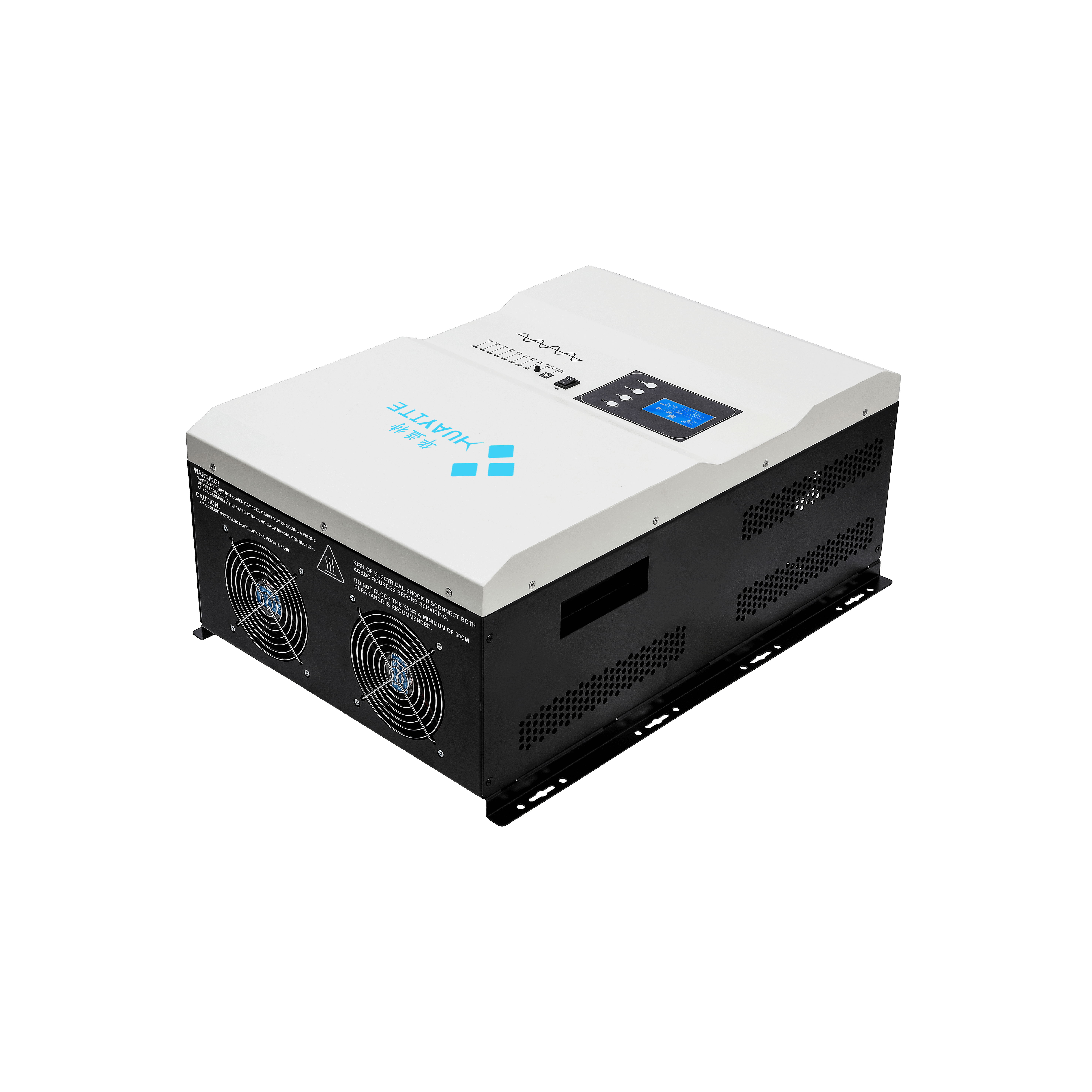
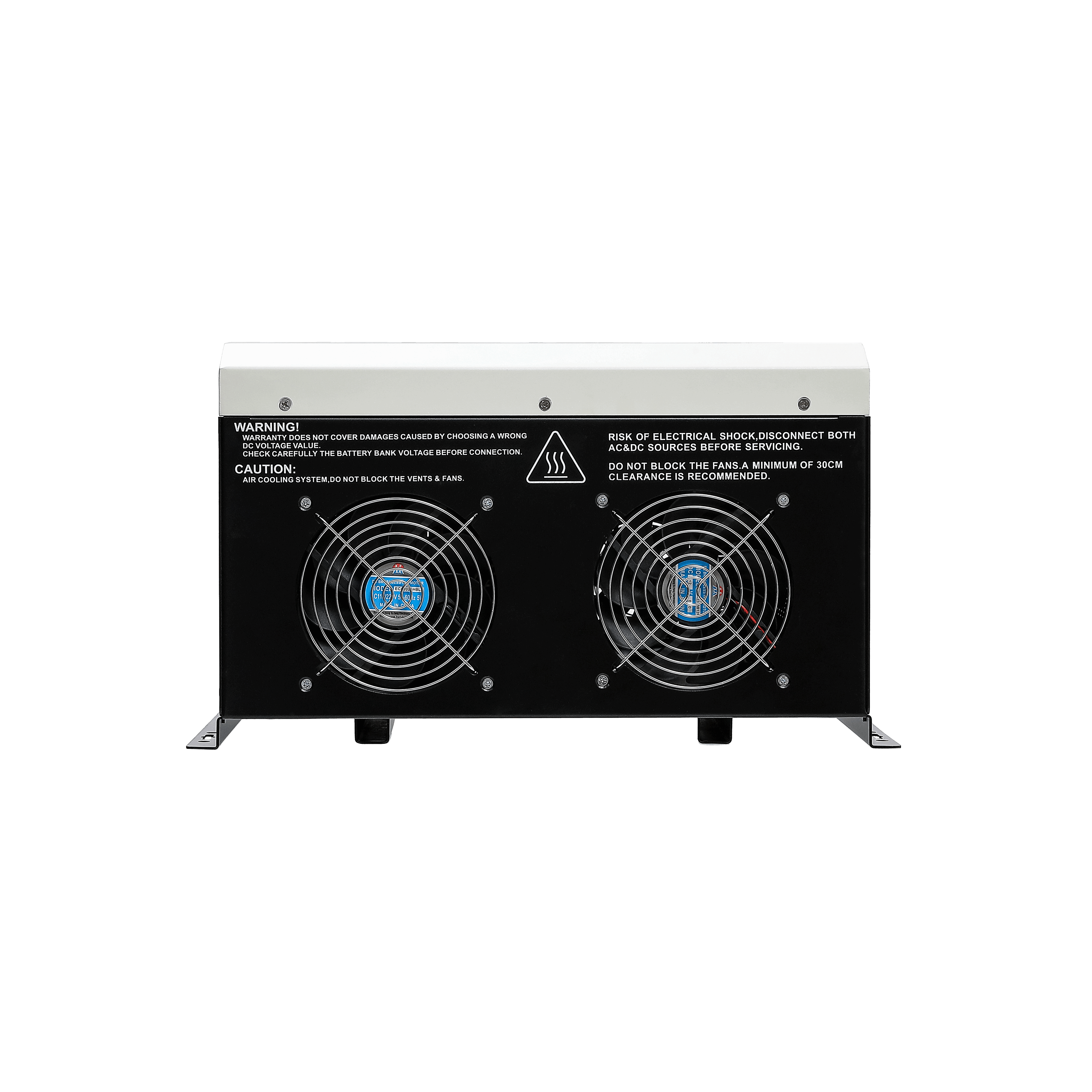
The transformer also sets the physical rules. Net weight runs from 16 kg to 61.5 kg depending on rating, so the wall, rack or plinth behind the unit has to be rated for the load, and the side heat sink and fan grilles need clear air. Do not block the vents or the fans, and leave working clearance in front of the panel for service.

Related Models

For solar inverter suppliers building a project pipeline, this series covers the heavy end of our off-grid range: 1kW to 12kW, low frequency, built for motor loads and sites with no reliable utility. Around it we build high-frequency hybrid inverters for grid-interactive projects, MPPT charge controllers and wall-mounted LiFePO4 battery systems, so an order can be put together as a complete off-grid package instead of an inverter on its own. Because the same solar inverter manufacturer builds the charger, the battery and the inverter, the DC side is specified together: the charge profile matches the bank, the controller matches the array, and the protection thresholds are set once. For a lighter duty — a cabin, a caravan, a single room — the HX-PV Series wall-mounted inverter in the same range is the smaller alternative. This series is the one to specify when surge, motor starting or continuous duty is the deciding factor on site.

Output, AC Input & Protection

Output waveformPure sine wave / same as input (bypass mode)
Inverter efficiency (peak)>88%
Line mode efficiency>95%
Power factor0.9-1.0
Nominal output voltage (RMS)100V / 110V / 120VAC or 220V / 230V / 240VAC ±5% (RMS); 220V / 230V / 240VAC ±5% (RMS) on the higher-voltage models
Output frequency50Hz ± 0.3Hz/60Hz ± 0.3Hz
Typical transfer time10ms(max)
Short circuit protectionYes (1sec after fault)
AC input voltage100V / 110V / 120VAC or 220V / 230V / 240VAC; 220V / 230V / 240VAC on the higher-voltage models
Selectable AC input range90-135VAC or 154-264VAC; 154-264VAC on the higher-voltage models
Input frequency range50Hz / 60Hz
Input voltage waveformSine wave (grid or generator)
Max input AC voltage300VAC for 230VAC HV mode
Max bypass current15A

Battery & Charger Settings

  • Battery system voltage. 12/24/48VDC, 24/48VDC or 48VDC depending on the rating. Confirm the bank voltage against the model before wiring: connecting a bank in the wrong charge mode is not a recoverable mistake.
  • Minimum start voltage. 10.0Vdc / 10.5Vdc in 12Vdc mode, doubled for 24Vdc and quadrupled for 48Vdc.
  • Low battery alarm and cut-off. Alarm at 10.5Vdc / 11.0Vdc in 12Vdc mode, cut-off at 10.0Vdc / 10.5Vdc, both scaled ×2 for 24Vdc and ×4 for 48Vdc.
  • High battery alarm and recovery. Alarm at 16.0Vdc and recovery at 15.5Vdc in 12Vdc mode, again ×2 for 24Vdc and ×4 for 48Vdc.
  • Battery initial voltage for start. 10-15.7Vdc in 12Vdc mode, ×2 for 24Vdc and ×4 for 48Vdc.
  • Charger output voltage. Depends on battery type, so the charge mode is set for the chemistry actually installed rather than carried over from a previous project.
  • Charging power. Max charge power rate is one third of the unit's rating power, so as an off grid solar inverter charger it does not push a small bank at full output.
  • Charger AC input breaker rating. 15A / 20A / 30A / 42A / 42A / 42A / 63A / 80A / 80A, in order from 1kW to 12kW.
  • Sizing the bank behind it. The off grid solar battery system sets the autonomy: a larger bank buys runtime but also takes longer to bring back up, so the bank and the inverter rating are chosen together.

Use Scenarios

  • Telecom base stations and remote wireless sites. Where the grid is intermittent or absent, this off grid pure sine wave inverter holds radio and transmission equipment on a stable supply, absorbs the start-up surge of cooling fans without tripping, and reports through the remote interface so an operator does not send a technician for every event. A solar array and a diesel generator can both feed the charger. - Rural electrification and village power. Household and small-enterprise loads far from a substation run from a PV array and a battery bank, with the inverter supplying the AC side. Its low-frequency stage keeps motor-driven loads such as pumps and mills inside the same mini-grid. - Irrigation, farm and workshop duty. A 3kW or 4kW unit runs a borehole pump through the day on solar and hands over to a generator during a cloudy week; larger ratings drive workshop machinery and cold-room compressors alongside lighting. - Home backup in weak-grid areas. For a single dwelling the same cabinet works as a solar inverter for home backup — lights, refrigeration, fans, television and a water pump on one battery bank, with grid or generator recharging the bank whenever it is available. - Small commercial and light industrial backup. Shops, clinics, cold rooms and small workshops run it as a straight UPS: the load stays on the inverter output and the mains does nothing but charge.

Model Range & Power Output

ModelContinuous outputSurge ratingMotor startingN.WG.W
HS1000W1.0 kW3,000 VA1 HP16 kg19 kg
HS2000W2.0 kW6,000 VA2 HP20 kg22 kg
HS3000W3.0 kW9,000 VA3 HP26.5 kg29.5 kg
HS4000W4.0 kW12,000 VA4 HP31.5 kg38 kg
HS5000W5.0 kW15,000 VA5 HP33.5 kg40 kg
HS6000W6.0 kW18,000 VA6 HP37.5 kg44 kg
HS8000W8.0 kW24,000 VA8 HP56.5 kg63.5 kg
HS10000W10.0 kW30,000 VA10 HP58.5 kg66 kg
HS12000W12.0 kW36,000 VA12 HP61.5 kg68.5 kg
ItemDetail
MountingWall mount
Machine dimension (W × H × D)380 × 375 × 200 mm / 425 × 375 × 200 mm / 560 × 420 × 235 mm / 655 × 490 × 240 mm (four cabinet sizes across the range)
Package dimension (W × H × D)460 × 495 × 300 mm / 500 × 495 × 300 mm / 660 × 470 × 310 mm / 720 × 470 × 290 mm
Operating temperature-10°C to 40°C
Storage temperature-15°C to 60°C
DisplayLED + LCD
Container loading, 20GP509 / 378 / 291 / 286 pcs, in the same four cabinet groups
Container loading, 40GP1,054 / 783 / 604 / 592 pcs, in the same four cabinet groups
Container loading, 40HQ1,236 / 919 / 708 / 694 pcs, in the same four cabinet groups

System Diagram & Wiring

  1. Solar array to the charge controller. PV strings feed an MPPT or PWM controller sized to the array; the controller regulates charging into the bank independently of the inverter, which is what lets the array keep working while the inverter is off. 2. The diagram uses a 12V/200Ah bank as its worked example; the terminal layout is the same at 24V and 48V. Check the bank voltage before connection and set the charge mode to match. 3. Grid or generator to AC input. A sine wave supply from the grid or a diesel set enters the AC input through its own breaker, with the selectable input range chosen by DIP switch for the local supply. 4. 5. 6. 7. Where the chain ends. This is an off grid solar inverter, so the chain finishes at the load panel — there is no grid-export function to coordinate with the utility.

Advanced Features

  • DIP-switch setup on the front end. Battery undervoltage point, input AC range, energy-saving mode and priority mode are all selected by DIP switch, so a technician can match one cabinet to a lead-acid or lithium bank on site without a laptop.
  • Battery/AC priority. The unit can be set to run the load from the solar-charged battery first with the grid held in reserve, or from the grid first with the battery kept back; the same setting decides when the charger engages.
  • Generator start support. A generator start function brings a diesel set into operation when the battery reaches its low-voltage alarm, so charging continues from the generator instead of draining the bank further.
  • Energy-saving mode. With a light load the inverter reduces its own draw, which matters on a battery-only site where every watt of self-consumption comes straight out of the bank.
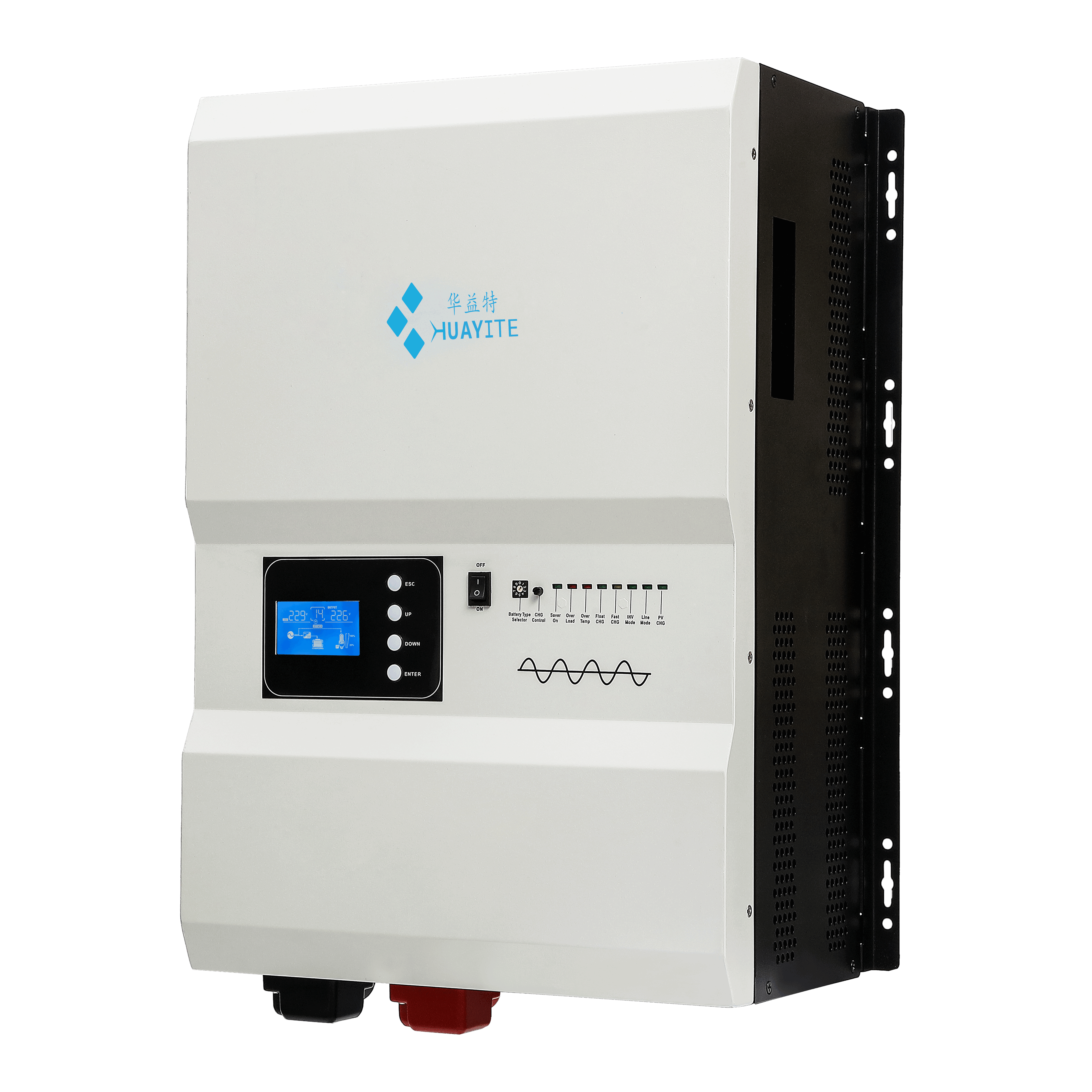
  • Local and remote monitoring. The front panel pairs an LCD with an LED row for battery power, charge, fault, inverter, line and bypass states. A remote control panel and RJ11 / RJ45 / RS232 / RS485 interfaces are optional, PC software monitoring is supported, and a WiFi or 4G module extends the same data to app-based cloud monitoring.
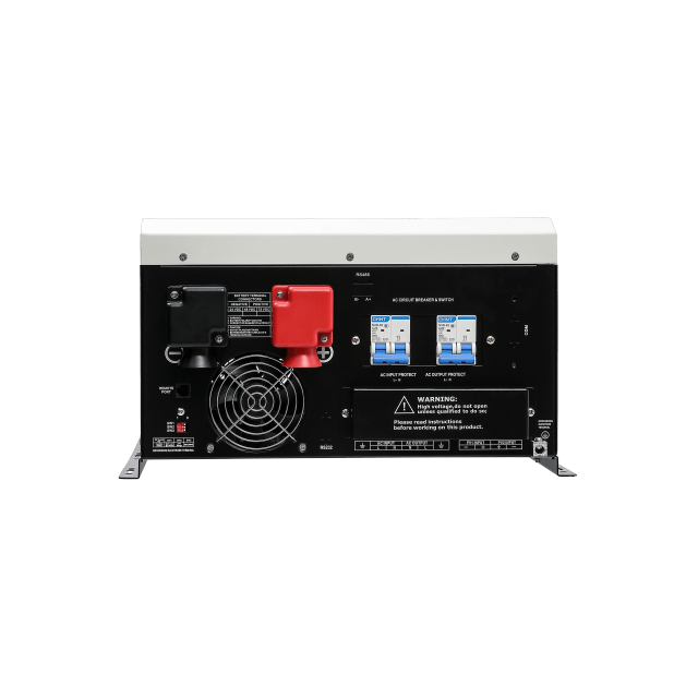
  • Protection on both AC sides. AC input and AC output each have their own circuit breaker inside the cabinet, overload and output short circuit are handled by circuit breakers, and the DC terminals sit behind red and black covers so isolation for service does not depend on an external panel.

Ordering & Delivery

  1. Send the load list. Distributors and solar inverter suppliers usually start here: continuous kW, the largest motor or compressor, the battery bank voltage and chemistry, and the number of backup hours the site needs. 2. Fix the model and configuration. We come back with the rating, the DC settings and the options that fit — remote control panel, RJ11 / RJ45 / RS232 / RS485 interfaces, or a WiFi / 4G module. 3. Confirm the commercial terms. Minimum order quantity, mixed-model container rules, payment terms and Incoterms are agreed with your sales contact for each order. 4. Check the documents the project needs. If the site is specified against a particular standard, tell us which one and we will confirm which test documents are available for the model before you commit. 5. Production and lead time. Standard models ship in 3-7 days; customized orders take 15-30 days. 6. Warranty. Every unit carries a 2-year warranty, and the same team handles commissioning questions, fault diagnosis and spare parts afterwards. 7. Packing and shipping. Each unit is cartoned at the gross weight shown for its rating, and container loading is quoted per cabinet size for 20GP, 40GP and 40HQ. Confirm shipping terms and export documents with your sales contact. - Datasheet. Continuous and surge output, motor starting capacity, battery voltages, efficiency, dimensions, weights and container loading for all nine ratings — the file solar inverter suppliers usually forward to installers before a project is quoted. - Installation manual. Mounting and clearance, AC and DC wiring, DIP-switch settings, charge-mode selection and start-up checks, with the terminal layout for each rating. - System diagram. The full power path from array and generator through the charger and bank to the AC load panel, including breaker positions. - Battery setting reference. The 12V threshold table with the ×2 and ×4 scaling for 24V and 48V, so a technician can set a bank up without recalculating. - Order documents. The configuration sheet and packing list for the exact rating, options and battery profile on your order, issued for approval before production.

Technical Support & Model Matching

Choosing the right unit for a site starts with a conversation, not a catalogue number. Share your load profile, battery voltage and backup requirement, and our engineers will help you match a model from our full range and confirm the accessories that go with it. The same Shenzhen-based team, with in-house R&D and more than 20 years in the industry behind them, stays with you after delivery: wiring and commissioning guidance, fault diagnosis, and spare-part support for units already in service. For private-label projects, they also handle artwork and specification approvals before production.

FAQ

Why choose a low frequency inverter rather than a high-frequency model?

A low frequency inverter carries a U-type transformer between the DC input and the AC output. That gives galvanic isolation, real thermal mass and the ability to absorb the start-up current of motors and compressors that a lighter switching stage cannot take. The trade-off is weight and size — this range runs from 16 kg to 61.5 kg net — so specify it where surge and continuous duty matter, and choose a high-frequency model where cabinet space and weight are the harder constraint.

Is the AC output a true sine wave?

Yes. In inverter mode the output is a pure sine wave, and in bypass mode it follows the input waveform, which should itself be a sine wave from the grid or the generator. Power factor and frequency tolerance are tight enough for motors, instrumentation and switch-mode supplies to share one distribution board, which is what makes this an off grid pure sine wave inverter rather than a modified-wave unit.

What does the charger do when the grid or generator comes back?

It switches to charging instead of simply passing the load through. As an off grid solar inverter charger, the unit rectifies the incoming AC to charge the bank, while the priority setting decides whether the load stays on the inverter or moves to bypass. The charge profile follows the battery type selected for the bank, so a lead-acid bank and a lithium bank are not charged on the same setting.

How large should the off grid solar battery system be?

Work back from the load and the autonomy the site needs: multiply the continuous kW by the hours it must run without sun or generator, then add margin for inverter losses and for the depth of discharge your chemistry allows. The bank also has to accept the recharge the inverter can deliver, so a very large bank behind a small inverter will come back up slowly after an outage. Send the load profile together with the bank you have in mind and we will check the match.

Will this work as a solar inverter for home backup?

Yes, provided the house has a battery bank — this is a battery-based design, not a grid-tied one. A typical single-dwelling installation runs lighting, refrigeration, fans, a television and a water pump from the bank, with the grid or a generator recharging it. Size the rating on the simultaneous load rather than on everything in the house, and let the bank carry the hours the grid is down.

Can this off grid solar inverter run with no battery connected?

No. The battery bank is the energy source during an outage; the charger keeps that bank up from the grid or generator, and the inverter converts from the bank. If a site genuinely has to run without storage, tell us the load and the duty cycle and we will confirm what the platform can and cannot do for that case.

How is the unit installed, and what clearance does it need?

It is wall mounted, with the AC and DC terminations on the rear panel and the controls on the front. The side heat sink and fan grilles must be left unobstructed, and working clearance in front of the panel is needed for service. Operating temperature is -10 °C to 40 °C, storage -15 °C to 60 °C, and the largest cabinets weigh 61.5 kg net, so the wall or frame has to be rated for it. We recommend a qualified installer for the AC and DC connections.

What maintenance does it need in service?

Very little beyond keeping the air path clear — blocked vents and dusty fan grilles are the usual cause of overheating on a remote site. Battery terminals and DC connections should be checked at each service visit, and the fault log can be read through RS232/485 or the optional WiFi/4G module, which often means a fault is diagnosed before anyone travels. Manuals and wiring documents come with every unit, and our engineers support commissioning and troubleshooting remotely.

Can I choose the battery voltage and add remote monitoring?

Battery system voltage is fixed by the rating — 12/24/48VDC, 24/48VDC or 48VDC — so the model and the bank are chosen together rather than separately. Remote monitoring is a separate option: a remote control panel, RJ11 / RJ45 / RS232 / RS485 interfaces, or a WiFi / 4G module for app-based cloud monitoring. Tell us which of them the site needs when you specify the model.

Advanced Features

Battery/AC priority: Combines effortlessly with grid power, diesel generators, or other sources

Significant Cost Saving: Achieves 3-5% higher efficiency

Superior Overload Capacity: Handles 3x rated power surges

Clear System Monitoring: LCD+LED Dual Display, WIFI/4G remote control

Pure Sine Wave & Isolated Design

Advanced Remote Management (Optional): RJ11/RJ45/RS232/485
System Diagram


Download