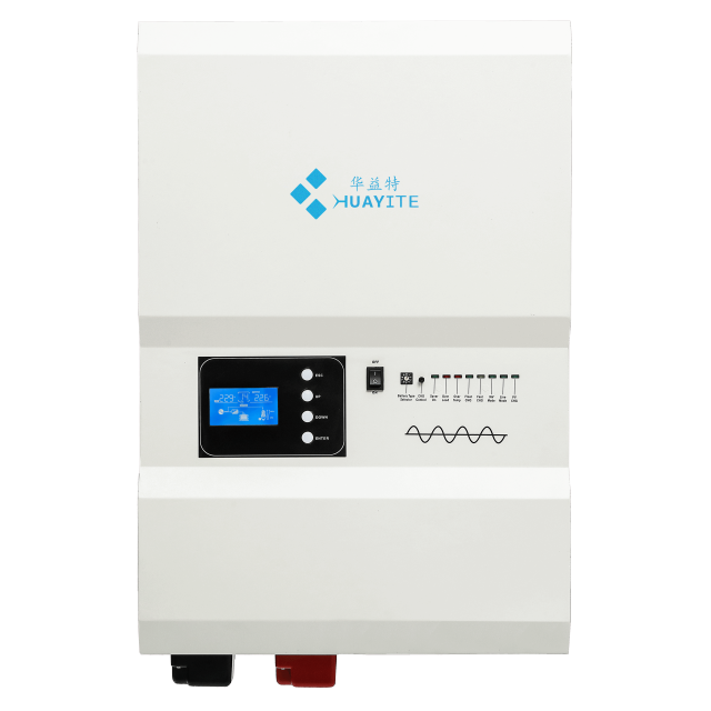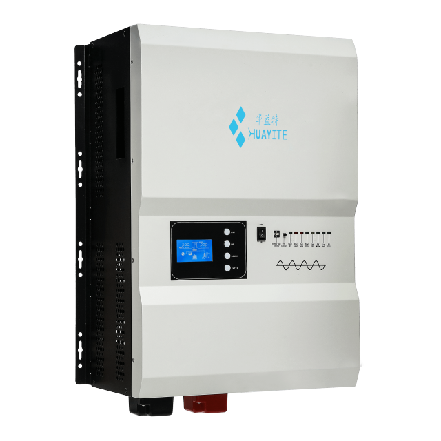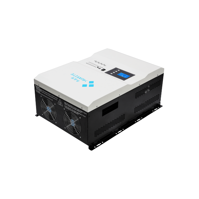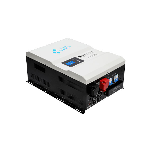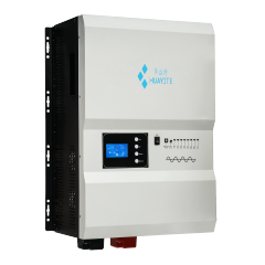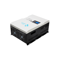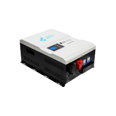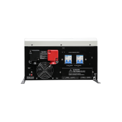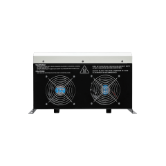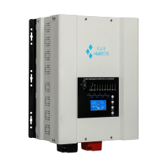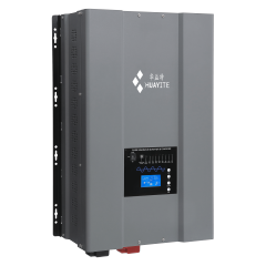
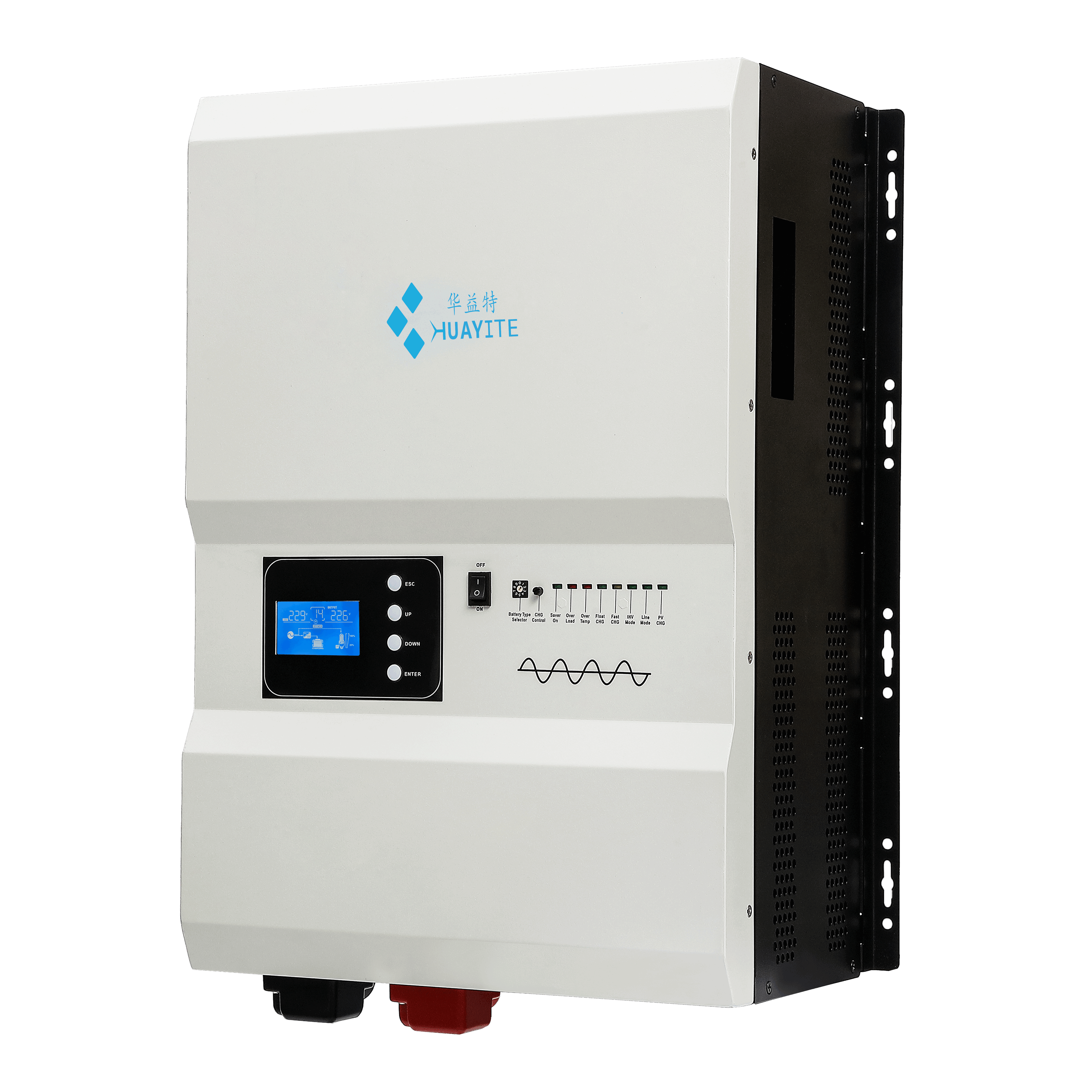
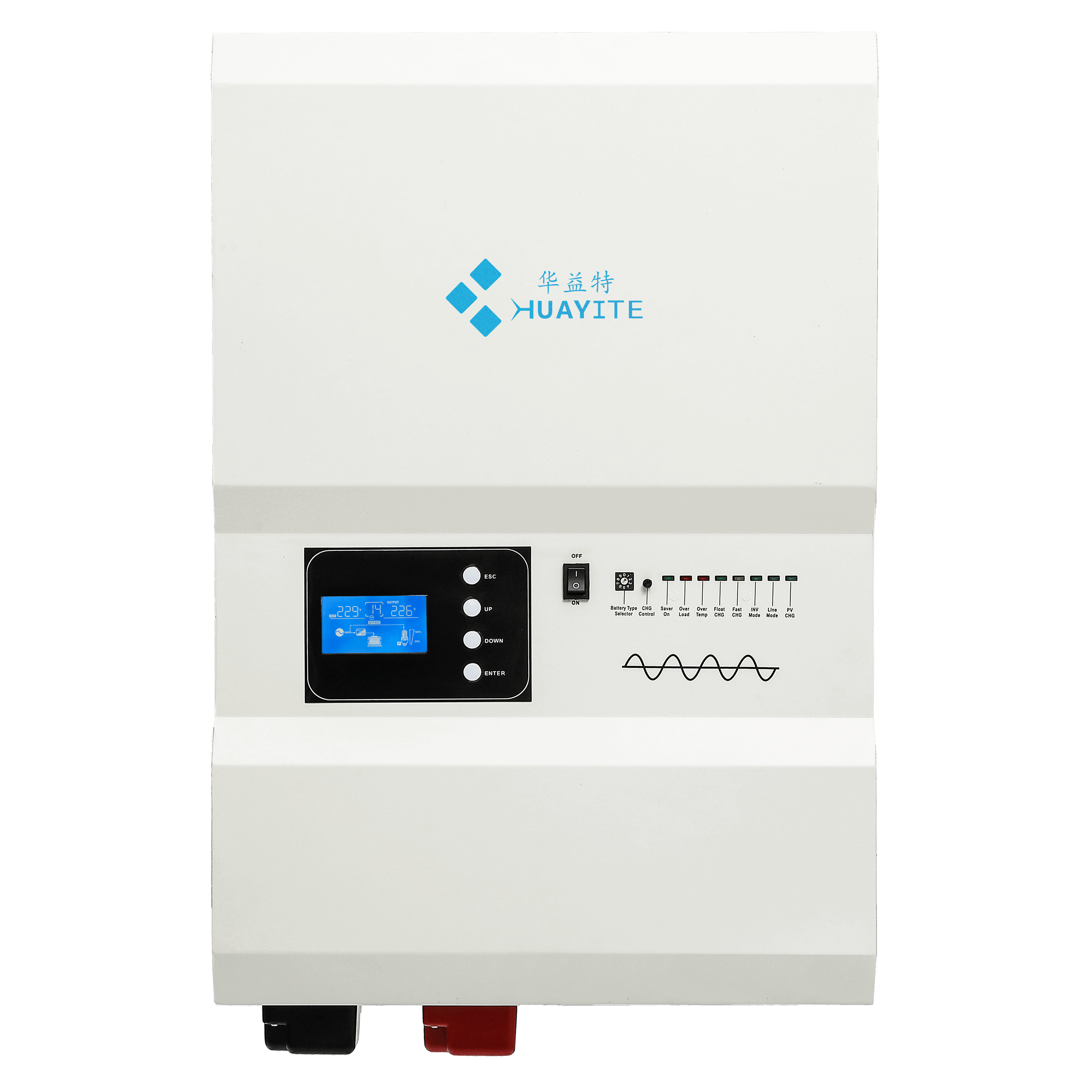
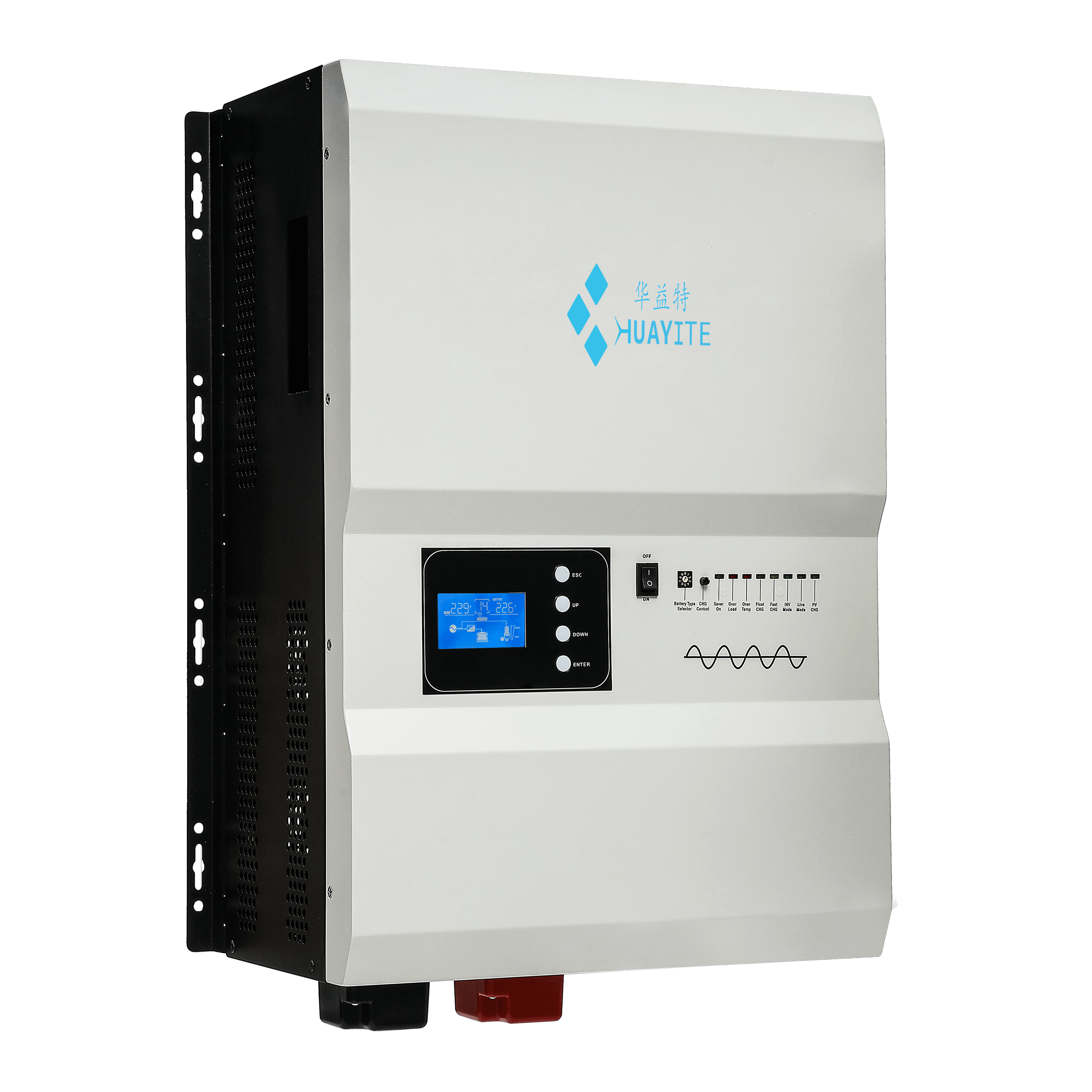
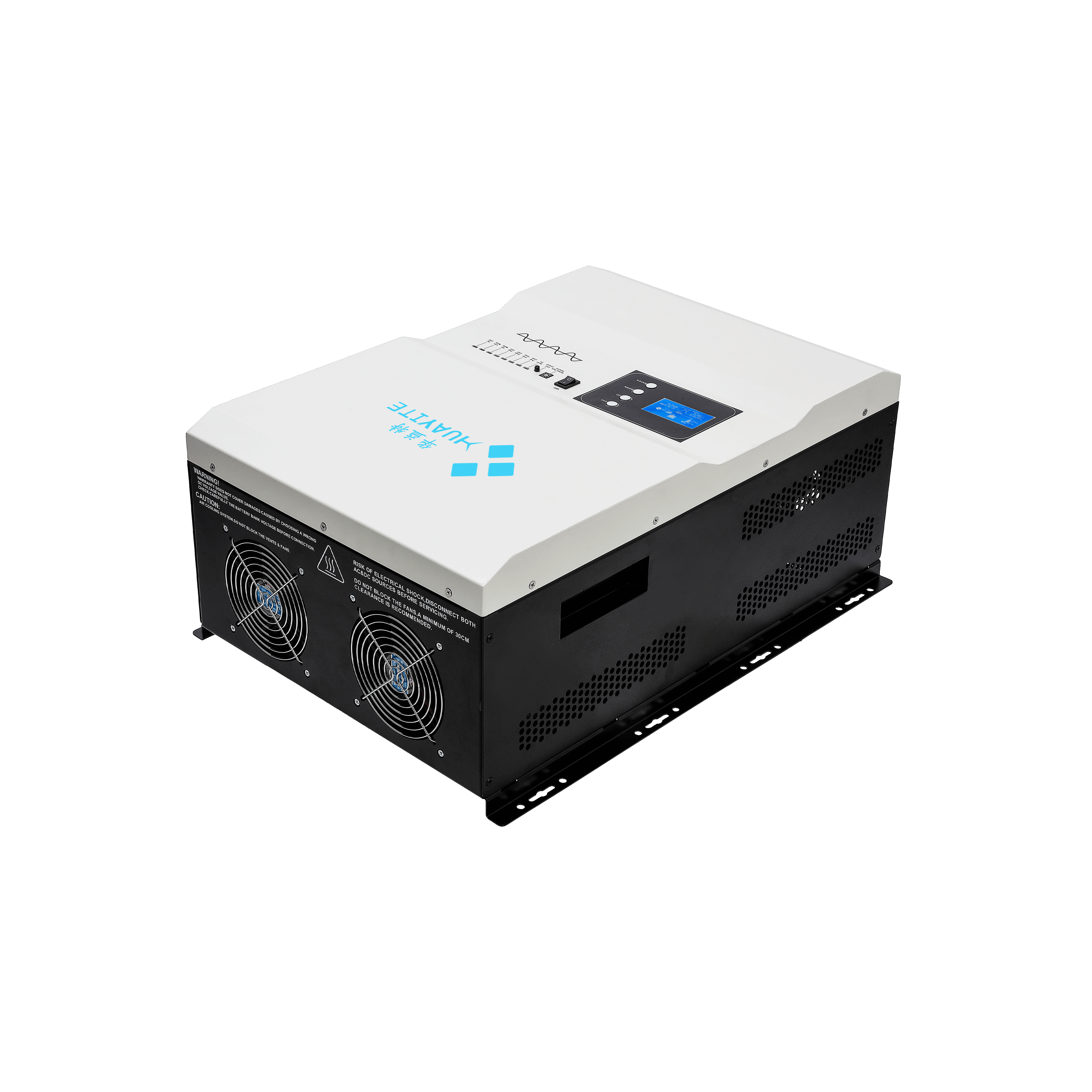
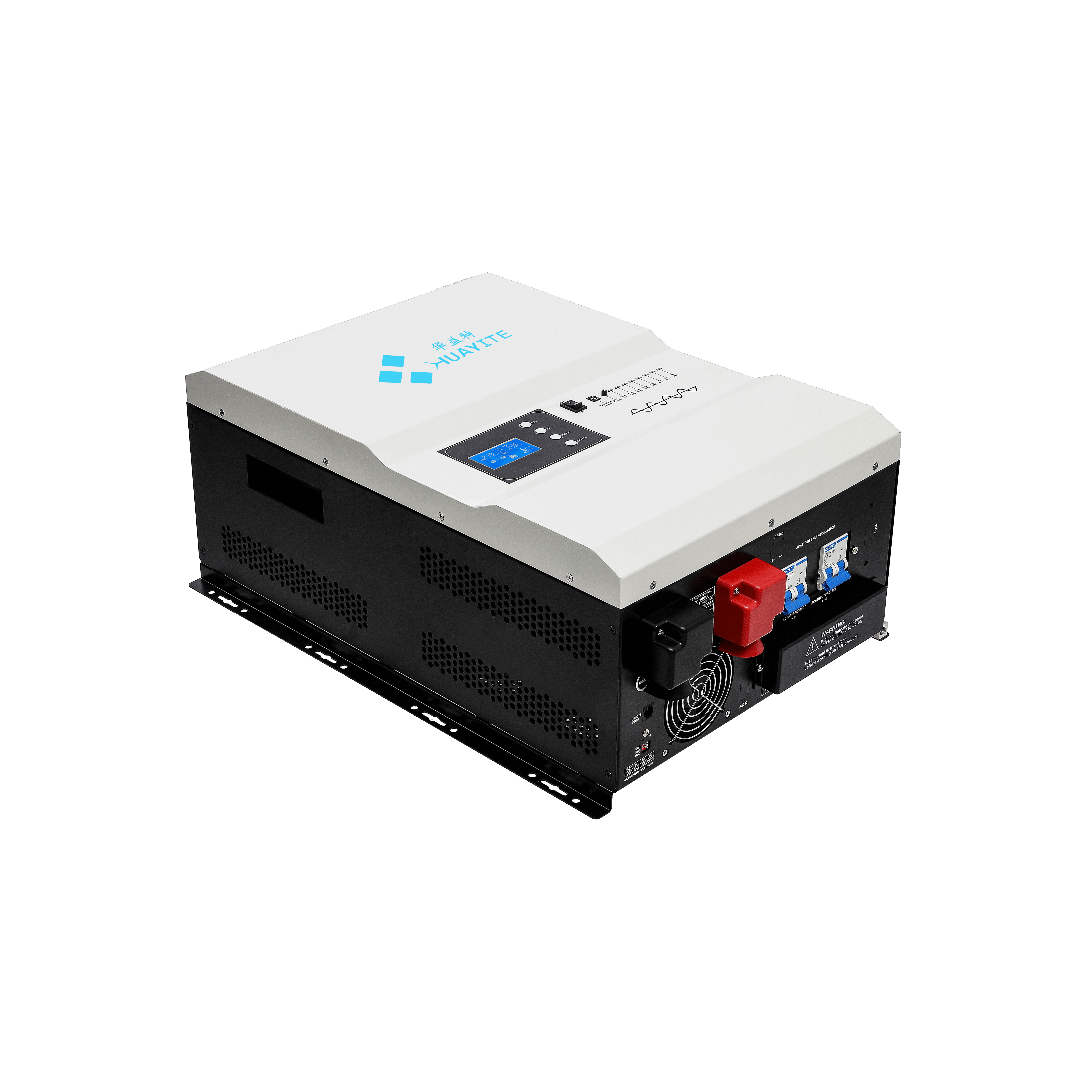

• HK-PV Series 1-12KW Low Frequency Split Phase Inverter.
  • HK-PV Series 1-12KW Low Frequency Split Phase Inverter.
  • HK-PV Series 1-12KW Low Frequency Split Phase Inverter.
  • HK-PV Series 1-12KW Low Frequency Split Phase Inverter.
  • HK-PV Series 1-12KW Low Frequency Split Phase Inverter.
  • HK-PV Series 1-12KW Low Frequency Split Phase Inverter.
  • HK-PV Series 1-12KW Low Frequency Split Phase Inverter.
  • HK-PV Series 1-12KW Low Frequency Split Phase Inverter.
  • HK-PV Series 1-12KW Low Frequency Split Phase Inverter.
  • HK-PV Series 1-12KW Low Frequency Split Phase Inverter.
  • HK-PV Series 1-12KW Low Frequency Split Phase Inverter.
  • HK-PV Series 1-12KW Low Frequency Split Phase Inverter.
  • HK-PV Series 1-12KW Low Frequency Split Phase Inverter.
  • HK-PV Series 1-12KW Low Frequency Split Phase Inverter.
  • HK-PV Series 1-12KW Low Frequency Split Phase Inverter.
  • HK-PV Series 1-12KW Low Frequency Split Phase Inverter.
  • HK-PV Series 1-12KW Low Frequency Split Phase Inverter.
  • HK-PV Series 1-12KW Low Frequency Split Phase Inverter.

HK-PV Series 1-12KW Low Frequency Split Phase Inverter.

No.HK-PV Series


Contains four functions of mains bypass, mains charging, inverter,UPS,
fully automatic switching
 The efficiency is 3~5% higher than the ordinary power frequency series, and the self-consumption
is reduced by 30~50%
   DIP switch selection: battery undervoltage point, input AC range, energysaving mode, priority mode.
   Remote communication interface RJ11/RJ45/RS232/485 remote control panel (optional)
   Support PC software monitoring, support WIFI 4G module expansion to realize app cloud
monitoring (optional)
Pure sine wave output, input and output completely isolated design.
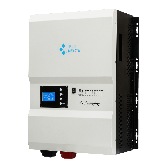


  • HK-PV Series 1-12KW Low Frequency Split Phase Inverter.
  • HK-PV Series 1-12KW Low Frequency Split Phase Inverter.
  • HK-PV Series 1-12KW Low Frequency Split Phase Inverter.
  • HK-PV Series 1-12KW Low Frequency Split Phase Inverter.
  • HK-PV Series 1-12KW Low Frequency Split Phase Inverter.
  • HK-PV Series 1-12KW Low Frequency Split Phase Inverter.
  • HK-PV Series 1-12KW Low Frequency Split Phase Inverter.
  • HK-PV Series 1-12KW Low Frequency Split Phase Inverter.
  • HK-PV Series 1-12KW Low Frequency Split Phase Inverter.

Description

Product Overview

A split phase inverter charger carries the whole site on its back: utility, generator, PV and battery all meet at its terminals, and the loads downstream expect that meeting to be invisible. This one keeps mains bypass, mains charging, a pure sine wave power inverter stage and UPS switching inside a single cabinet, so a 120/230 VAC panel stays live whether power is arriving from the grid, a generator or the battery bank.

Nine ratings cover 1 kW, 2 kW, 3 kW, 4 kW, 5 kW, 6 kW, 8 kW, 10 kW and 12 kW. That spread lets one low frequency inverter platform serve a cabin, a small commercial unit and a light industrial line without changing brands halfway through a project — and gives solar inverter suppliers a single family to hold instead of four.

Under the cover sit a low-loss U-shaped transformer and a fully isolated input/output stage. The DC side accepts 12, 24 or 48 VDC nominal banks, and the built-in MPPT charger lets a PV array work alongside the mains charger rather than compete with it.

Most sites that buy this model share one requirement: no gap between utility failure and backup. Industrial and commercial facilities, off-grid homes on split-phase distribution, and hybrid PV installations all depend on the same four behaviours — automatic switching, stable voltage, enough headroom for motor starts, and a charger that treats the battery properly.

- Industrial and commercial facility backup. A workshop, cold room or production line that cannot take an outage uses the unit as both UPS and conversion stage: the panel runs from the inverter when the utility drops, and the charger rebuilds the bank once it returns. - Split-phase residential and light commercial off-grid. Homes and small businesses on split-phase distribution get two voltage classes from one off grid pure sine wave inverter, so 120 V branch circuits and 230 V equipment share a single battery bank instead of needing two systems. - PV-first hybrid sites. Where the sun carries most of the load, the MPPT charger feeds the bank through the day and the inverter draws on it at night, with the mains charger covering long cloudy spells. - Generator-assisted installations. Sites that already run a diesel or petrol set use the inverter as the primary supply and the generator as a top-up source, which cuts generator hours, fuel burn and noise. - Motor-heavy loads. Pumps, compressors, refrigeration and workshop machinery draw several times their running current at start; the low-frequency transformer and the surge headroom are what let a split phase inverter charger of this size start them without stalling. - Replacement and upgrade work. Where an older inverter has failed and the panel wiring stays, the same split-phase output and 12/24/48 VDC input let the unit drop into an existing installation with the battery bank and changeover arrangement untouched.
HK-PV Series 1-12KW Low Frequency Split Phase Inverter.
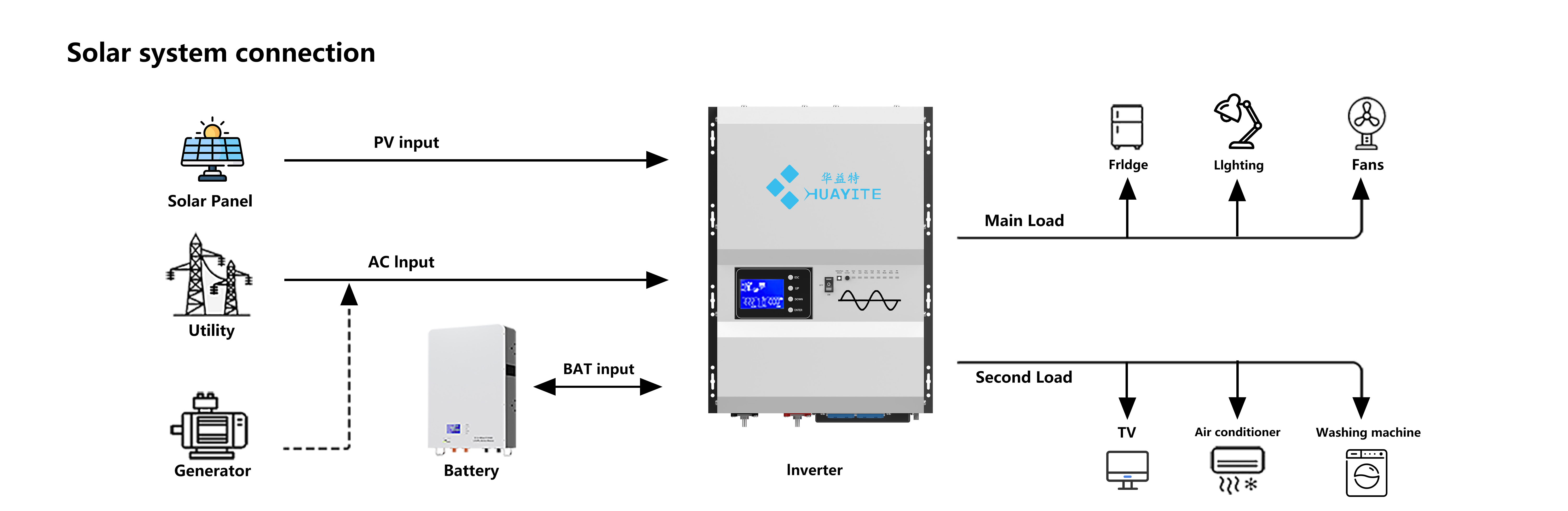
Solar system connection diagram with inverter, panel, utility, generator, battery

Product Advantages

Fewer boxes on the wall. Mains bypass, mains charging, inversion and UPS switching are one product, not four. That removes a changeover panel, a standalone charger and the interconnecting wiring between them, along with the failure points each of those brings to a site that has to stay up — the combination to look for when you compare pure sine wave power inverter suppliers.

A transformer that wastes less. The low-loss U-shaped transformer lifts efficiency 3-5% above an ordinary power frequency inverter and cuts self-consumption by 30-50%. On a site that runs around the clock, that difference shows up in the battery bank at the end of the night, not only on a specification sheet.

Clean, isolated output. Every load is fed by a pure sine wave power inverter stage with fully isolated input and output. Motors run cooler, electronics see no switching artefacts, and the waveform is close enough to the utility supply that nothing has to be derated for it.

Load capability matched to real sites. Surge headroom covers compressor and pump starts, and the overload and short-circuit logic trips on a defined curve instead of dropping the panel the instant something inrush-heavy comes on line.

A generator is a first-class source. The AC input takes a sinusoidal generator waveform and complements the mains when both are present, so a site that already runs a diesel set keeps it as the third source instead of retiring it.

Split-Phase Output & Dual-Voltage Wiring

  • Two live legs, two voltage classes. Nominal output is LV 120 Vac ±10% rms or HV 230 Vac ±10% rms; loads wired across the two live legs see the higher voltage, loads taken from either leg to neutral see the lower one, and one pure sine wave inverter charger feeds both.
  • Balance the legs where you can. Keep the 120 V circuits roughly even between the two live legs. A panel with all the lighting on one leg and all the motors on the other runs warmer than it should and gives away transformer capacity for nothing.
  • Changeover is fast enough to hold a load. Transfer takes 15 ms at most, which is short enough to keep controllers, servers and refrigeration compressors running through the gap instead of restarting.
  • Confirm the supply arrangement before wiring. Split-phase distribution and 110/220 V three-wire systems are not the same thing, and the neutral arrangement decides how the output should be landed. Send us the utility voltage, the number of live conductors and whether a neutral is present, and we will confirm the configuration for the site.
  • Isolated in, isolated out. The DC and AC sides never share a reference. That is what makes the output behave like a utility supply rather than an approximation of one, and it is why the unit can sit between a battery bank and a panel without a second isolation transformer.
  • One output, two sources. On bypass or on battery, the panel sees the same nominal voltage and the same waveform — the transfer changes where the power comes from, not what the load experiences.
  • The AC terminal is an input, not an export. Power flows from the utility or the generator into this split phase inverter charger, and from the battery bank out to the loads. Nothing is pushed back up the line, so there is no export limiter, no anti-backflow relay and no net-metering function to enable. - Say it before the paperwork does. A project that promises net metering, a feed-in tariff or a signed interconnection agreement needs a grid-interactive hybrid, not this unit. If that requirement appears halfway through a tender, raise it early and we will point you to the model in the range that carries it. - Approvals are granted by the destination market, not by a datasheet. Utility interconnection and market-entry rules are written per country, sometimes per utility. Send the exact reference — grid code number, utility rule or tender clause, with the edition — together with the destination country and the rating you intend to ship, and we will confirm in writing which certificates, test reports and declarations can be supplied with that model. We do not claim compliance with a standard we cannot put in front of you. - 110/220 V three-wire sites need the supply described before wiring. Settle four things at enquiry: the nominal utility voltage, the number of live conductors, whether a neutral is present, and where neutral and earth are bonded. Split-phase distribution, a three-wire 110/220 V service and a two-wire 230 V feed are landed differently, and the output neutral treatment has to match the panel. Give us those details and the configuration is confirmed in writing before the unit ships. - 60 Hz markets are the design case. North American and Caribbean sites run at 60 Hz, and the output is set to 60 Hz ±0.3 Hz for them, while the input accepts 51-64 Hz so a slightly fast or slow generator still passes. Check the setting at commissioning rather than assuming it left the factory matched to the site. - No utility at all is a normal installation. Where the only AC source is a diesel or petrol set, it connects to the AC input as the charging and bypass source and the inverter carries the panel the rest of the time. That arrangement needs no utility approval, but it does need the generator's voltage and frequency written down, because a set that swings outside the input window will cause repeated transfers.

AC Input & Output Specifications

ParameterRating
Input voltage waveformSinusoidal (utility or generator)
Nominal input voltage120/230 VAC
Low line disconnect85 Vac ±4% (Normal) or 80 Vac ±4% (Wide) at 120 Vac; 184 Vac ±4% (Normal) or 135 Vac ±4% (Wide) at 230 Vac
Low line re-connect95 Vac ±4% (Normal) or 85 Vac ±4% (Wide) at 120 Vac; 194 Vac ±4% (Normal) or 145 Vac ±4% (Wide) at 230 Vac
High line disconnect136 Vac ±4% (Normal) or 140 Vac ±4% (Wide) at 120 Vac; 263 Vac ±4% (Normal) or 263 Vac ±4% (Wide) at 230 Vac
High line re-connect131 Vac ±4% (Normal) or 135 Vac ±4% (Wide) at 120 Vac; 253 Vac ±4% (Normal) or 253 Vac ±4% (Wide) at 230 Vac
Maximum AC input voltage120 Vac models: 150 Vac maximum; 230 Vac models: 270 Vac maximum
Input frequency50 Hz: 41-54 Hz / 60 Hz: 51-64 Hz
Output voltage waveformSine wave
Power factor0.9-1.0
Nominal output voltageLV: 120 Vac ±10% rms; HV: 230 Vac ±10% rms
Nominal output frequency60 Hz ±0.3 Hz / 50 Hz ±0.3 Hz

Charging, Solar Input & Protection

  • Five charger settings for five bank sizes. Nominal charge current is selectable at 20 A, 35 A, 50 A, 70 A or 90 A with regulation held to ±5 Adc, so a single pure sine wave inverter charger covers a small 12 V bank and a large 48 V bank without adding an external unit.
  • Three-stage profile. Boost CC (constant current) into Boost CV (constant voltage) into Float. The bank takes bulk current while it is empty, a controlled finish as it fills, and a float hold that keeps it there.
  • Over-charge protection that announces itself. Above 15.5 VDC on a 12 V bank, 31.0 VDC on a 24 V bank or 62.0 VDC on a 48 V bank, the unit beeps 0.5 s every 1 s and raises a fault after 60 s.
  • MPPT solar charging is built in. The internal controller is rated 40 A or 60 A depending on model, so the array charges through the same cabinet instead of a separate box on the wall.
  • The array voltage has to match the bank. Maximum PV open-circuit array voltage is 40 Vdc on 12 V systems, 55 Vdc on 24 V systems and 110 Vdc on 48 V systems — check the array's Voc at the lowest expected temperature before connecting anything.
  • Set the profile before the first connection. A wrong charge profile is the most common way a perfectly good battery gets damaged. Confirm bank voltage and chemistry, dial the charger in, then land the DC cables.
  • Parameter | Rating --- | --- Nominal DC input voltage | 12 / 24 / 48 VDC Low battery alarm | 10.5 VDC ±0.3 (12 V) / 21 VDC ±0.6 (24 V) / 42 VDC ±1.2 (48 V) Low DC input shutdown | 10 VDC ±0.3 (12 V) / 20 VDC ±0.6 (24 V) / 40 VDC ±1.2 (48 V) High DC alarm and fault | 16 VDC ±0.3 (12 V) / 32 VDC ±0.6 (24 V) / 64 VDC ±1.2 (48 V) Surge rating (10 s) | 1:3 (VA) Overload protection | 110% load > 150%: beeps 0.5 s every 1 s, fault after 20 s Output short-circuit protection | Current limit, fault after 10 s Load protections | Low battery, over-charge, overload, over-temperature Power saver | Load-dependent saving, switched at the configuration block Efficiency | ≥97%; ≥85% in battery mode; >96% in line mode Operating temperature | 0 °C to 40 °C Storage temperature | -15 °C to 60 °C Operating humidity | 5% to 95%, non-condensing Audible noise | 60 dB max

Advanced Features

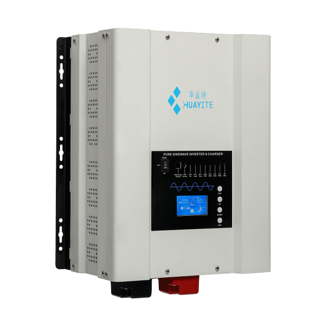
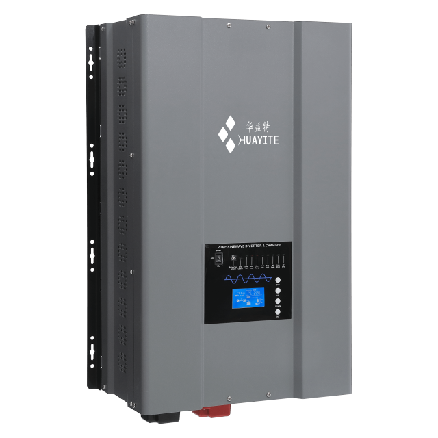
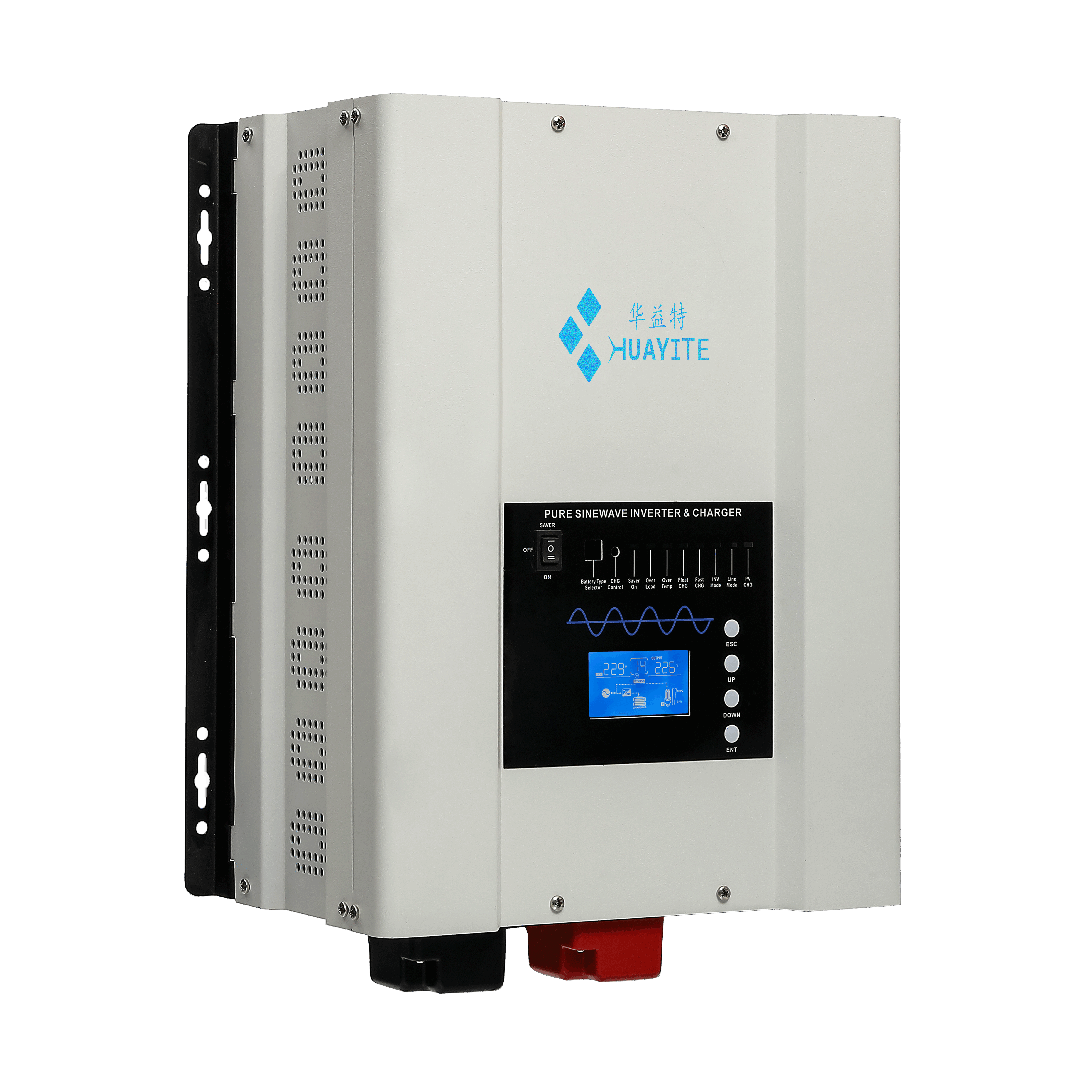
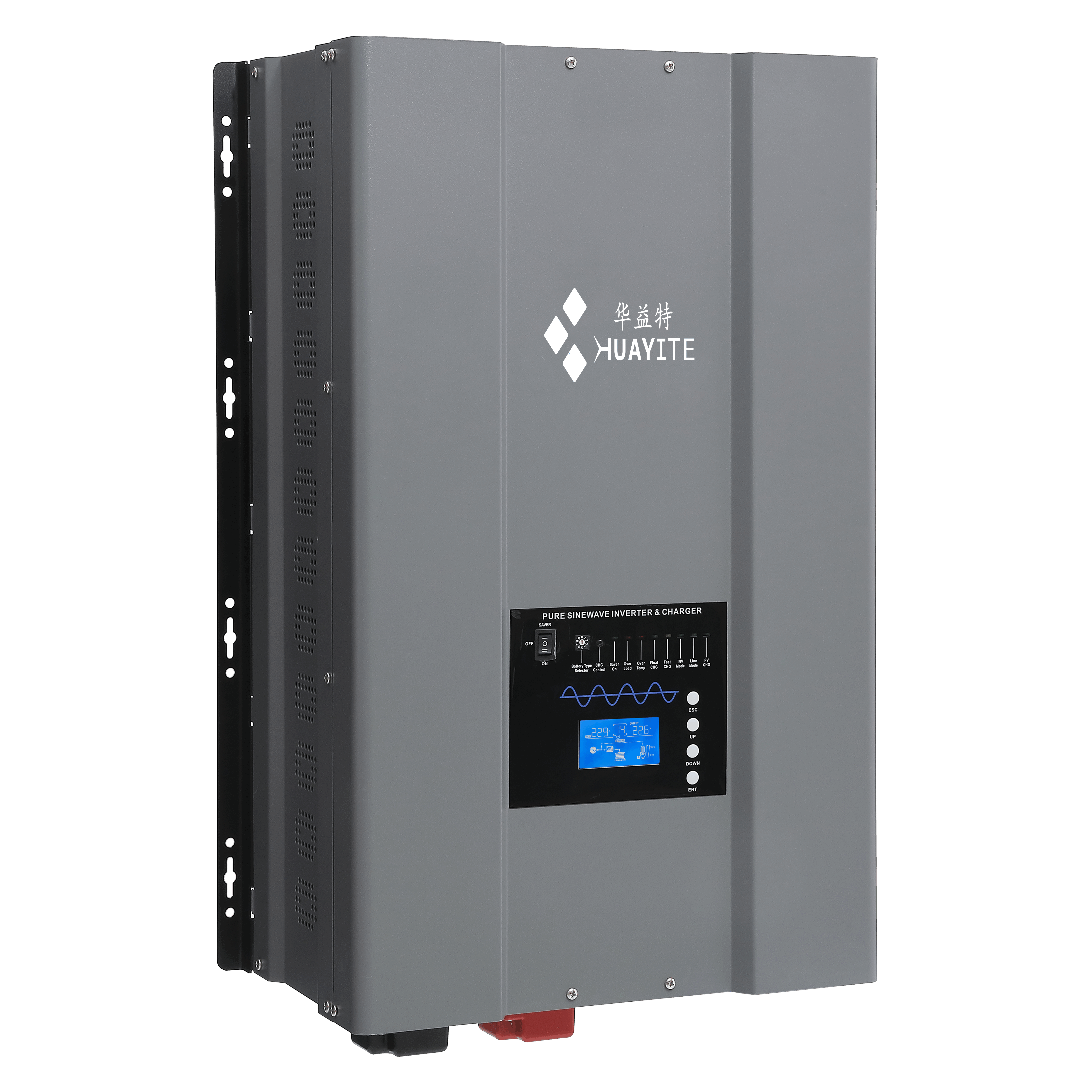
A front panel that answers questions. The LCD readout pairs with four keys — ESC, UP, DOWN and ENTER — for setup and live readings, so an installer can confirm output voltage and frequency on the spot instead of carrying a meter to every commissioning.

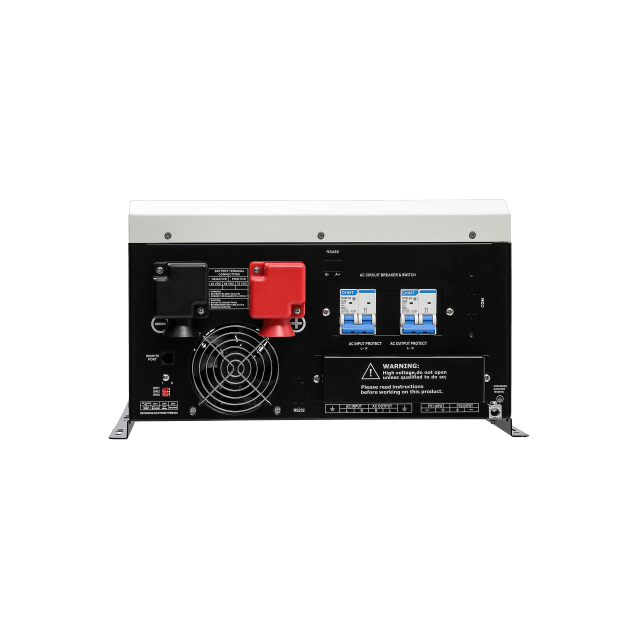
A status bank that narrows the fault. Nine LEDs cover the states that matter in service: BATT, CHG, SYS, OVD, OVT, FAU, LOW, BYP and MUT. Reading which one is lit points a technician at the battery, the charger, the temperature or the bypass before any test equipment comes out of the van.

DIP switches for site conditions. Battery undervoltage point, AC input range, energy-saving mode and priority mode are all set at the switch block rather than in software, which means a service visit can retune the unit without a laptop or a licence.

Remote monitoring, wired or wireless. A dedicated remote port plus RJ11, RJ45 and RS232/485 interfaces support a remote control panel, PC-based monitoring, or an optional WiFi/4G module for app and cloud access. These are options on the standard build, so specify the combination you want when the order is placed.

Energy-saving mode for light night loads. With the mode enabled, the unit trims its own draw when the connected load falls away — worth having on an off-grid house running a fridge and a few lights between midnight and dawn.

Installation & Commissioning

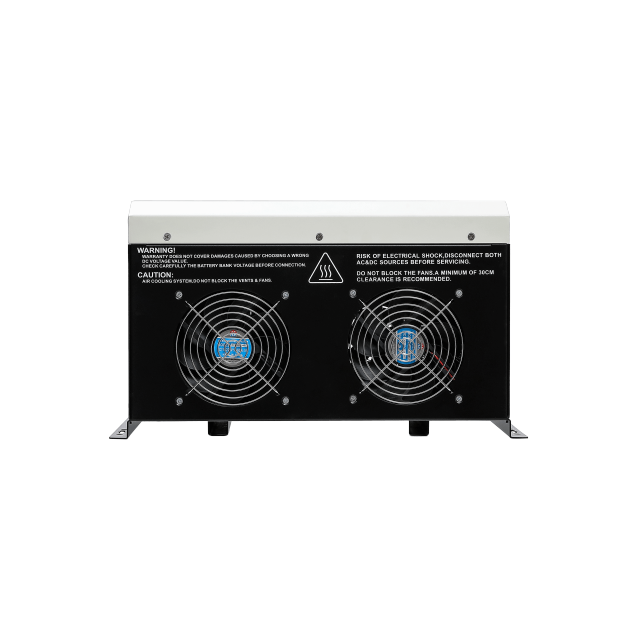
  1. Plan the position. Leave at least 30 cm clear in front of the fans and vents, keep ambient inside 0-40 °C, and mount on a wall or in a rack using the brackets supplied. Cabinet sizes across the range are 340×420×200 mm, 425×375×200 mm, 560×420×235 mm and 655×490×240 mm depending on rating, with net weight running from 16 kg at the 1 kW end to 61.5 kg at 12 kW — because this is a low frequency inverter, plan a two-person lift for the larger frames.
  2. Record the battery bank before touching the DC terminals: nominal voltage, chemistry and the manufacturer's recommended charge voltages. These decide the charger settings.
  3. Set the configuration switches — input range, battery undervoltage point, priority mode and energy-saving mode — while the unit is still isolated and no cables are live.
  4. Wire the DC side: battery positive to the positive terminal, negative to the negative terminal, with the polarity checked twice and a disconnect device on the bank. Cable size and torque follow the current rating of the model you ordered.
  5. Connect the PV array to its input, confirming open-circuit voltage stays inside the limit for the bank voltage, then connect AC input and AC output through their own breakers, matching the panel's live, neutral and earth conductors.
  6. Power up with no load and read the display. Output voltage and frequency should match the site, and no fault LED should be lit.
  7. Add load in stages — resistive first, then motors — and confirm the unit holds voltage through each start. Log the settings used so the next service visit begins from a known baseline.
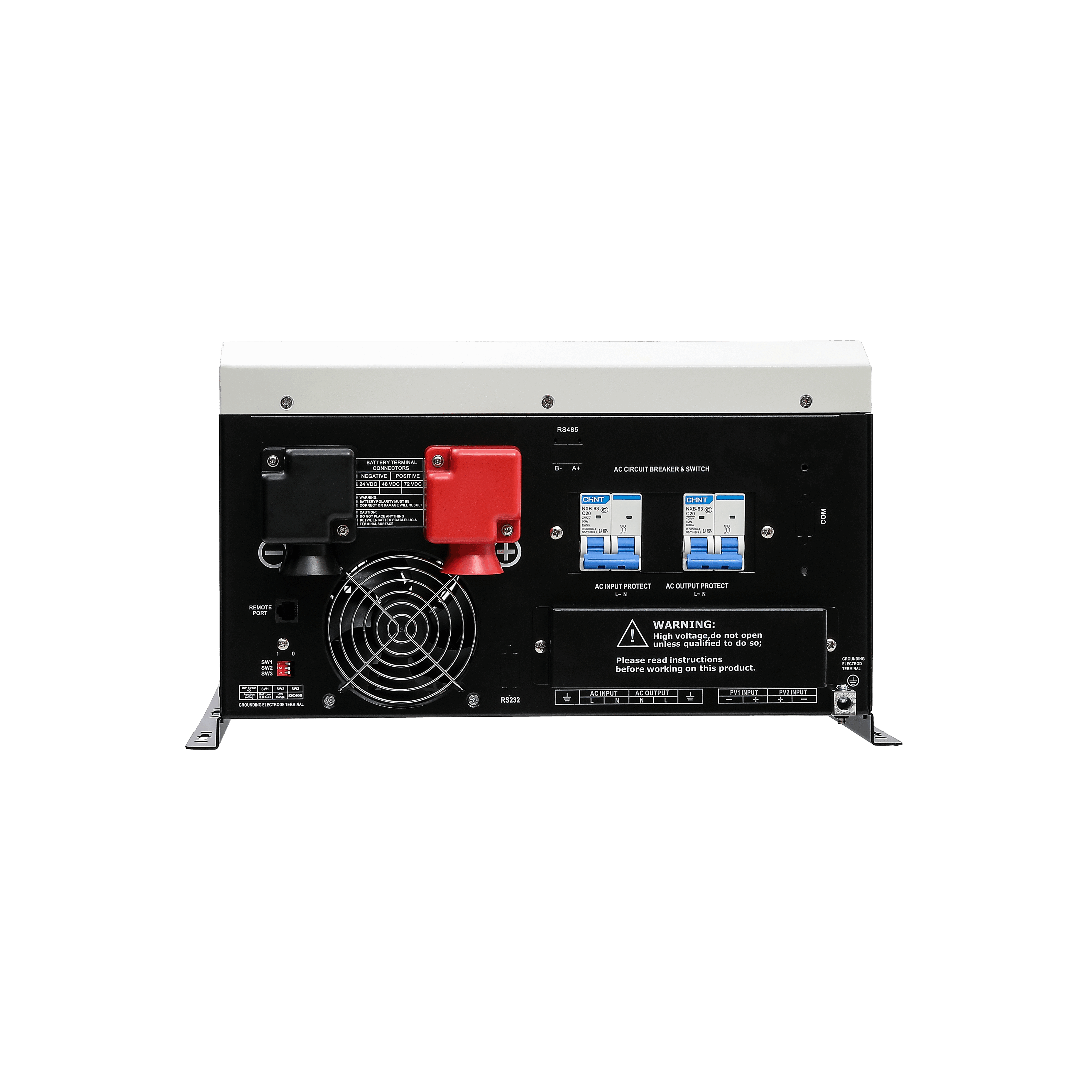
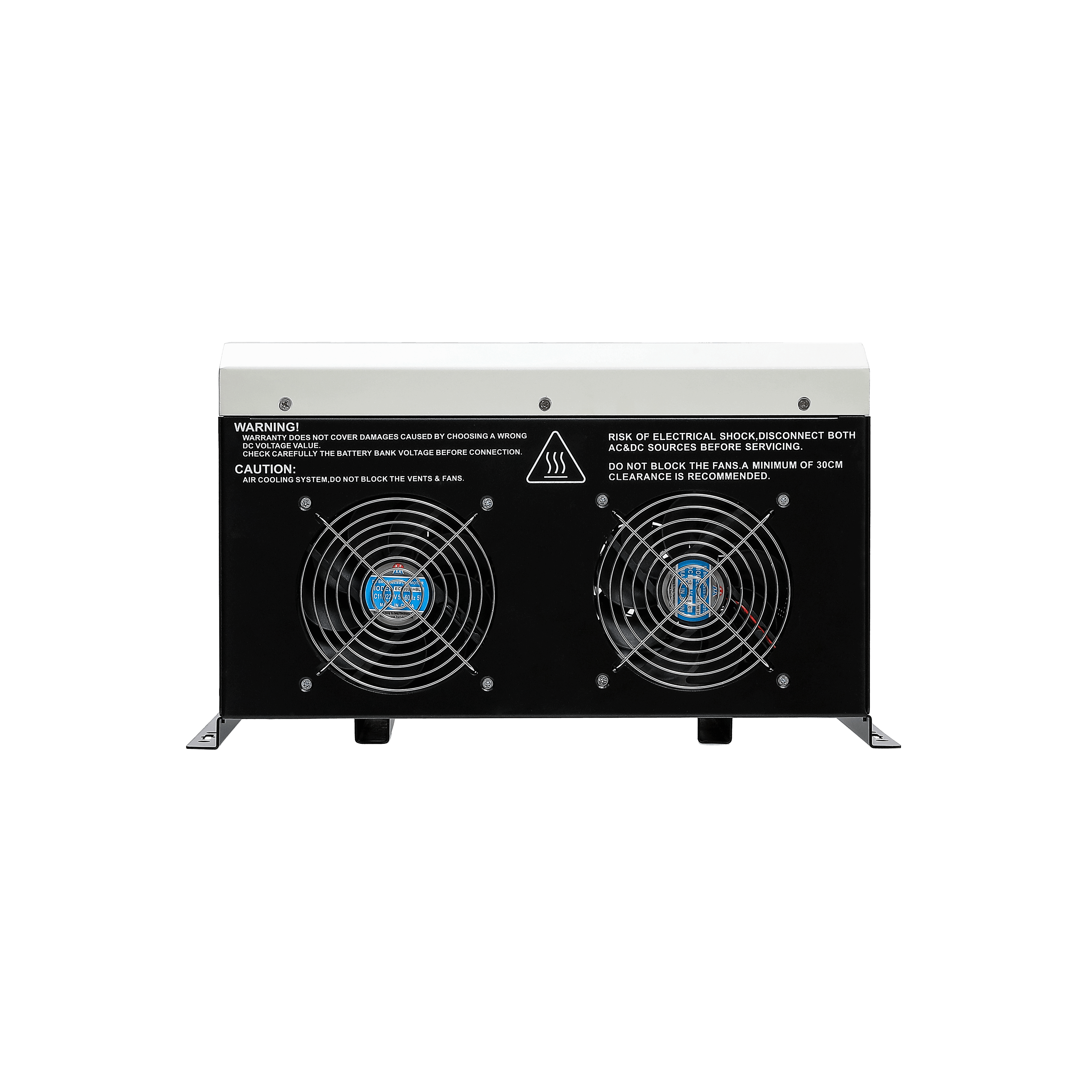
  8. Four connections define the system. A PV array lands on the MPPT charger input, the battery bank connects to the DC terminals marked for positive and negative, AC input arrives from the utility or the generator through its own breaker and switch, and the split-phase AC output leaves through a second breaker to the load panel. Follow the energy and the logic is simple: sun or mains current charges the bank, the bank feeds the pure sine wave power inverter stage, and the transfer stage decides which AC source reaches the loads at any moment. The charger decides separately whether the bank is being topped up from the array or from the utility, which is why a site can run solar-first in summer and mains-first through a bad week without rewiring anything. The rear panel keeps power and data apart. AC input protection, AC output protection and the main breaker sit together on one side; the remote port, RS485, USB, CAN and battery-monitoring connections sit on the other, away from the live conductors. Battery terminals are marked and covered so tools do not bridge them during service. The cabinet also carries its own safety instructions — high voltage inside, isolate both AC and DC before servicing, do not block the fans, keep 30 cm of clearance. Those labels matter most when the unit is handed to a maintenance team that did not install it. For an off grid pure sine wave inverter installation, the same layout doubles as the panel schedule: array, bank, AC input, AC output. If you need the drawing as a separate file for a project folder, ask for it and it will go out with the order documentation. The design can support flexible voltage outputs and a generator start function, with modular communication options for monitoring and control configurations. OEM/ODM customization and production batch orders can be discussed with the manufacturer.

OEM & ODM Customization

What is fixed and what flexes. The electrical platform — transformer, isolation, charging algorithm, protection thresholds — stays as designed, because that is what the field record rests on. Around it, the parts a brand actually wants to control are open: model designation, nameplate and manual, the language of the documentation, the mix of communication options, and the option set fitted to each build.

Why that matters for a private label. Launching a range under your own brand means the unit has to look and read like yours from the first container. Buyers comparing pure sine wave power inverter suppliers often find that OEM means a new sticker on the same box; the useful version is a documented configuration, a nameplate that matches the drawings, and a manual your installers can follow without calling you.

Building a range rather than a single model. Because one platform covers 1-12 kW, a brand owner can launch a small off grid pure sine wave inverter for cabins and a 12 kW unit for commercial sites from the same design language, the same accessory set and the same support story — which is what makes a range look deliberate rather than assembled.

Where solar inverter suppliers usually get this wrong. Customisation agreed verbally and never written into the production file is the classic failure. Agree the configuration in writing — model list, options fitted to each rating, documentation language and nameplate artwork — before the order is released, and the container that arrives matches the one you planned.

Distribution Support & Documentation

One family, several stock lines. A distributor covering 1 kW to 12 kW from a single platform carries one set of manuals, one accessory list and one training story, while still quoting a cabin job and a commercial job from the same catalogue. The 12/24/48 VDC input options widen that further, because bank voltage rarely stays uniform across a whole territory.

Documentation installers actually use. Each unit ships with a manual and a specification sheet; wiring diagrams and the configuration sheet for the build are available for installers planning a panel before the equipment lands. When a site needs a specific document for a tender pack, say so at the enquiry stage and we will confirm what can be supplied.

Service and spares at a distance. Ask about spare-part availability for the ratings you plan to carry, and keep the serial and configuration details for every unit you ship. Fault diagnosis starts from the panel's own status LEDs, which shortens the conversation between an installer on site and your technical desk.

Why the platform suits distribution. Efficiency gains and lower self-consumption matter to the end user's running cost, but the quieter advantage for a distributor is predictability: the same power frequency inverter architecture, the same protection thresholds and the same option set across nine ratings means fewer surprises in the field and fewer variants on the shelf.

Where it sits in a wider range. pure sine wave power inverter suppliers that also build MPPT controllers, lithium storage cabinets and smaller wall-mounted units can quote a whole system, but only if the pieces work together. This model shares its battery voltages and monitoring options with the rest of the range, so a mixed container makes sense. For loads below 1 kW, the HX-PV Series wall-mounted unit covers 350-1200 W from the same battery voltages.

Ordering & Delivery

  • Lead time. 3-7 days for standard models; 15-30 days for customized orders.
  • Warranty. 2-year warranty.
  • Order quantity. Agreed per project and model mix — share the ratings and option set you need and the quotation will be built around that.
  • Configuration check. Confirm the rating, the battery bank voltage, normal or wide AC input range, and the output configuration before the order is released.
  • Payment terms, shipping terms and packing. Confirmed with your sales contact for the destination and order size.
  • Samples and pre-production units. Ask your sales contact about availability for the configuration you are evaluating.
  • Two years, starting on a date you agree. Every unit in the HK-PV range carries a 2-year warranty. The start date matters as much as the length: a unit that sits six months in your warehouse before it is installed has already spent a quarter of its cover on a shelf. Agree whether the clock begins at invoice, at shipment or at commissioning, and have it written into the order confirmation. What the cover reaches and what it does not. The warranty covers the inverter itself. Batteries, PV cable, breakers and the rest of the balance of system are separate items with their own terms, and a failure caused by reversed DC polarity, a blocked fan grille or a lightning strike on the array is a site issue rather than a manufacturing one. Ask for the written warranty statement with the quotation so the exclusions sit in front of the buyer before the deposit, not after the failure. Who answers the phone under a private label. In an OEM build the end user calls the brand on the nameplate, not the factory. Settle before production who receives that first call, who authorises a replacement, whether a failed board comes back to us or is scrapped locally, and how the credit is raised. A distributor who never agreed these points ends up paying for a warranty it did not design. What a claim needs in order to move quickly. The serial number, the model, which LEDs were lit at the time of failure, the load that was connected and a photograph of the installation. Those five things usually separate a board fault from a wiring fault before anything is shipped, which is the difference between a two-week fix and a two-month argument. Keeping the right spares close. The parts that age in a power frequency inverter are the ones that move and the ones that switch — fans and control boards. Agree a small spares allowance with the first order for the ratings you intend to stock and hold it locally, so a fan swap costs a service visit instead of an air freight.

Technical Support & Model Matching

Choosing the right unit for a site starts with a conversation, not a catalogue number. Share your load profile, battery voltage and backup requirement, and our engineers will help you match a model from our full range and confirm the accessories that go with it. The same Shenzhen-based team, with in-house R&D and more than 20 years in the industry behind them, stays with you after delivery: wiring and commissioning guidance, fault diagnosis, and spare-part support for units already in service. For private-label projects, they also handle artwork and specification approvals before production.

FAQ

Can this unit be connected to the grid for net metering?

No. It is a standalone inverter charger: it takes AC from the utility or a generator, charges the battery and serves the loads, but it does not export power back to the grid, so net metering and anti-backflow arrangements do not apply to it. If a project requires a specific interconnection standard or utility approval, send us the standard number and the destination country before ordering and we will confirm which documents are available for that model. Where a grid-interactive hybrid is the right answer instead, tell us and we will point you at the correct unit in the range.

What happens when utility power returns?

The split phase inverter charger watches the input voltage and, once it settles inside the reconnect window, transfers the loads back to mains bypass while the AC charger takes over the battery bank. The inverter stage stops driving the panel at the same moment, so the two sources never fight each other. Priority mode decides what happens next — hold the bank at float for the next outage, or let solar take the lead and keep the mains charger as backup.

Which power rating should I order for my load list?

Add up the continuous running watts of everything that can be on at once, then allow margin for the largest motor start, because a pump or compressor can draw several times its running current for a second or two. A low frequency inverter copes with that inrush better than a high-frequency design, but the rating still has to suit the site. Send us the load list with running and starting watts, plus the split-phase voltage each load needs, and we will confirm the rating rather than leave you guessing.

Can I use a lithium battery bank?

Yes, with the settings matched to the bank. The charger offers five current settings and a three-stage profile, and a pure sine wave inverter charger of this size can be configured to a lithium bank's absorption and float targets. Send us the battery manufacturer's recommended charge voltages and the bank voltage before the order is released and we will confirm the configuration. Choosing a profile that does not match the bank is the one mistake this unit cannot protect you from.

The panel is showing a fault and the unit is beeping. What do I check first?

Start with whichever LED is lit. LOW points at the battery bank, OVD and OVT at over-voltage and over-temperature, FAU at a fault condition, BYP at bypass operation. Check the bank voltage against the alarm point for your DC voltage, confirm the fans are clear and the ambient is inside the operating range, then look at the load — an overload announces itself with a repeating beep before it latches. If the condition clears, the unit returns to service on its own; if it latches, note the LED pattern and the load at the time and take it to your service contact.

Is the output clean enough for sensitive electronics?

The output is a pure sine wave with fully isolated input and output, which is the right starting point for controllers, instrumentation and inverter-driven appliances. What we cannot do is guarantee compliance with a specific equipment standard without knowing which one it is — total harmonic distortion figures and medical or laboratory approvals are not part of the standard specification. Tell us what the equipment is and which standard the site applies, and we will confirm whether this model suits it or whether something else in the range does.

When should I specify the wide AC input range?

Choose it where the supply is not stable. On a solid utility feed the normal window is enough, and it keeps the unit from riding through sags it should not. On a generator-fed site, a weak rural feeder or an area with frequent brownouts, the wide window keeps the unit on mains for longer before transferring to battery — fewer changeovers, and less cycling on the battery bank.

Advanced Features

Energy-Saving Advantage: 3-5% higher efficiency
Intelligent Battery Charging
Clear System Monitoring: LCD+LED
Pure Sine Wave & Isolated Design
Builtin MPPT Solar Charger Controller: 30-120A
Advanced Remote Management (Optional): RJ11/RJ45/RS232/485
System Diagram


Download