

• HT Series 30A 40A 50A 60A 80A 100A 120A MPPT Solar charging controller  12V/24V/48V
  • HT Series 30A 40A 50A 60A 80A 100A 120A MPPT Solar charging controller  12V/24V/48V
  • HT Series 30A 40A 50A 60A 80A 100A 120A MPPT Solar charging controller  12V/24V/48V
  • HT Series 30A 40A 50A 60A 80A 100A 120A MPPT Solar charging controller  12V/24V/48V
  • HT Series 30A 40A 50A 60A 80A 100A 120A MPPT Solar charging controller  12V/24V/48V
  • HT Series 30A 40A 50A 60A 80A 100A 120A MPPT Solar charging controller  12V/24V/48V
  • HT Series 30A 40A 50A 60A 80A 100A 120A MPPT Solar charging controller  12V/24V/48V
  • HT Series 30A 40A 50A 60A 80A 100A 120A MPPT Solar charging controller  12V/24V/48V
  • HT Series 30A 40A 50A 60A 80A 100A 120A MPPT Solar charging controller  12V/24V/48V
  • HT Series 30A 40A 50A 60A 80A 100A 120A MPPT Solar charging controller  12V/24V/48V
  • HT Series 30A 40A 50A 60A 80A 100A 120A MPPT Solar charging controller  12V/24V/48V
  • HT Series 30A 40A 50A 60A 80A 100A 120A MPPT Solar charging controller  12V/24V/48V

HT Series 30A 40A 50A 60A 80A 100A 120A MPPT Solar charging controller 12V/24V/48V

No.HT Series


 Suitable for 12V/24V/36/48V systems, automatic identification system
   Voltage, parallel design and system capacity expansion.
   The four-stage charging improves the charging efficiency and improves the performance of the battery pack.
   The tracking efficiency of MPPT can reach 99.5% and the charging efficiency can reach 97.5%.
  Effectively extend the battery life, LCD screen and LED indicator display, can view any parameters and running status in real time
   Support PC software monitoring, support WiFl / 4G module expansion to achieve application cloud monitoring (optional)
   It can be used to charge all kinds of lead-acid batteries, gel batteries and the latest technology lithium batteries
  Perfect protection function makes the controller not easy to damage
   Dual fan cooling, economical structure design, low cost, benefiting more consumers


  • HT Series 30A 40A 50A 60A 80A 100A 120A MPPT Solar charging controller  12V/24V/48V
  • HT Series 30A 40A 50A 60A 80A 100A 120A MPPT Solar charging controller  12V/24V/48V
  • HT Series 30A 40A 50A 60A 80A 100A 120A MPPT Solar charging controller  12V/24V/48V
  • HT Series 30A 40A 50A 60A 80A 100A 120A MPPT Solar charging controller  12V/24V/48V
  • HT Series 30A 40A 50A 60A 80A 100A 120A MPPT Solar charging controller  12V/24V/48V
  • HT Series 30A 40A 50A 60A 80A 100A 120A MPPT Solar charging controller  12V/24V/48V

Description

Product Overview

The HT Series is a wall-mounted MPPT solar charge controller that sits between the PV array and the battery bank: it holds the array at its maximum power point and turns that output into a controlled charge. Models cover 30A, 40A, 50A, 60A, 80A, 100A and 120A, and each unit identifies the connected bank voltage on its own, so one part number serves a family of systems instead of a single fixed voltage. The front panel carries a circular LCD, an LED status indicator and four buttons — MENU/ESC, DOWN, UP and ENTER — for live readings of PV voltage and current, battery voltage, Ah, kWh and internal temperature without opening a laptop. As the charging link in an off grid solar battery system, this unit is often what decides how quickly a bank recovers after a week of cloud. Most go into homes on an off-grid or weak-grid supply, and into small commercial or agricultural arrays where several charge paths run side by side. Retrofit work is common too: installers and MPPT solar hybrid inverter suppliers add one when a hybrid inverter's own charger cannot keep up with an enlarged array. We build this MPPT solar controller alongside our inverter and battery ranges, so distributors and solar inverter suppliers can put a complete package together from one factory instead of matching parts from several. - Scalable parallel design: two controllers of the same voltage family can be tied to one battery bank, so a site that adds panels later adds a unit instead of replacing the one it already owns. - Dual fan cooling: two DC brushless fans on the rear panel pull air across the heat sink, keeping the power stage inside its temperature window through a long afternoon at rated current. - Four protections on the DC side: reverse polarity, short circuit, over-temperature at 85 °C and a hard current limit each act before the power stage is stressed, including the everyday site mistake of a reversed PV connection. - Front-access service design: screw-fastened cover, PV, battery, LOAD and RS485 terminals on the front block, and a side mounting flange — one technician can hang and wire the unit without a second pair of hands. - A true charge controller for solar panels: existing strings land straight on the PV input, the battery profile is set once, and the array is charging on the same visit, with no extra combiner or adapter. - Economical structure: a single wall-mount box with side ventilation slots, which keeps installation time and material cost down against rack-mounted hardware. - 12V solar charge controller that grows with the site: the 30A and 40A units handle a small 12V bank today and the same bank at 24V after an upgrade.
HT Series 30A 40A 50A 60A 80A 100A 120A MPPT Solar charging controller 12V/24V/48V
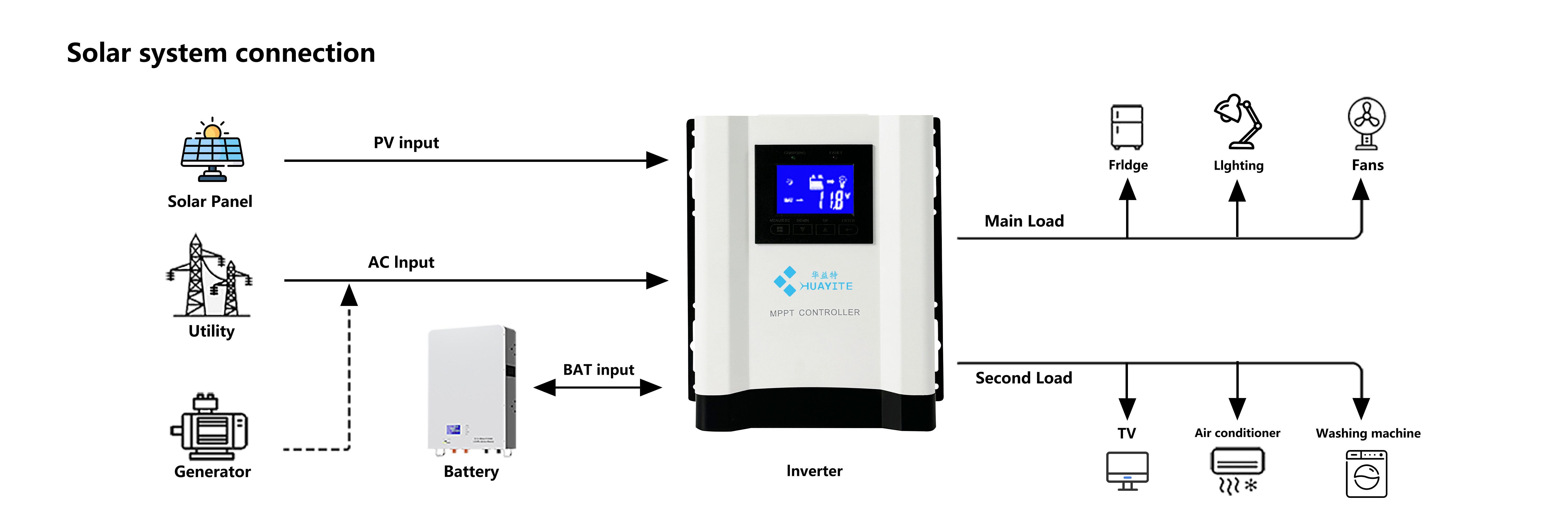
Diagram of solar, battery, AC and appliance connections to MPPT controllerHUAYITE MPPT inverter wiring diagram with solar panels, utility, battery, appliances

Advanced Features

Universal voltage compatibility

One solar panel charge controller covers a family of system voltages and sets itself to the bank it finds at connection — no selector, no re-strapping, no separate 24V variant to stock. 36V banks are recognised as well. A distributor carries fewer part numbers per container, and an installer carries a controller that works on the next site too. High MPPT efficiency In this MPPT charge controller, the tracker captures up to 99.5% of the power the array can deliver at its maximum power point, and the DC-DC stage converts it at up to 97.5% charging efficiency. The gain shows up in low light and in heat, where a controller that does not track sits well below what the array could actually produce. Ask our engineers for the measurement conditions, load points and conversion curves behind those figures if your tender needs them documented. Battery-state charging Charging follows battery state rather than a fixed timer: the controller works through its stages and then holds float, so a lightly loaded bank is not kept at absorption voltage for days on end. Real-time battery optimisation The LCD reports PV voltage and current, battery voltage and current, accumulated Ah and kWh, and internal temperature, and the same values stream over RS485 to the PC software for logging. Watching current taper as a bank approaches full is the quickest way to spot a failing string or a bank that has lost capacity. WiFi/4G cloud-ready remote control An optional WiFi or 4G module pushes those readings to a cloud dashboard, so a rooftop system in another region can be checked from a desk. That is the difference between hearing about a dead array at month end and seeing the charge current fall on the day it happens. Multi-battery compatibility Lead-acid, gel and lithium banks all run on the same unit, with lead-acid as the factory default. Gel and lithium profiles are selected on the panel, and the charge targets stay adjustable to the battery maker's data rather than being fixed at the factory.

Test Reports & Documents

DocumentWhat it coversWhen to ask
Model datasheetRated current, nominal battery voltage, maximum solar input voltage, MPPT window and maximum PV input power for every 12V, 24V, 48V, 72V and 96V bankWith the first enquiry, so the right charge controller for solar panels is fixed before the quotation
Efficiency test recordThe input voltage, load points and ambient temperature behind the 99.97% peak conversion efficiency and the 99.5% tracking figure, together with the conversion curve across the load rangeWhen a tender or a customer's technical file asks for the conditions rather than the headline number
Standard and test listThe standards the HT Series MPPT solar charge controller is tested against and the individual test items covered, model by modelBefore you quote a project that names a standard, so the status is confirmed in writing
Environmental complianceStatement covering the 2002/95/EC requirement and the absence of cadmium, hydride and fluorideFor customs and import documentation
Dimension and wiring drawingsCase outline, mounting centres, terminal layout and the PV / battery / LOAD / RS485 connection diagramFor panel layout, cable schedules and installation planning
PC software and RS485 mapThe monitoring application, the register list for the RS485 link and the setup steps for the optional WiFi or 4G moduleFor integrators writing their own logging or dashboard
Charge set-point sheetDefault float and average charge voltages for each model, and the range they can be re-set withinWhen the battery datasheet differs from the factory lead-acid default

Model Range & Sizing

  • 30A and 40A — 12V / 24V DC banks: 190 × 168 × 95 mm case, 2.2 kg net and 2.5 kg gross, in a 245 × 230 × 145 mm carton. The everyday 12V solar charge controller size for a cabin, a caravan or a small home bank fed by a handful of panels.
  • 50A and 60A — 12V / 24V / 48V DC banks: 245 × 190 × 95 mm, 3.2 kg net and 3.6 kg gross, in a 285 × 270 × 140 mm carton. The usual pick for an off grid solar battery system that may move from 24V to 48V without changing controller.
  • 80A, 100A and 120A — 48V / 72V / 96V DC banks: 320 × 235 × 130 mm, 7.4 kg net and 7.9 kg gross, in a 355 × 315 × 176 mm carton. Built for larger home storage and small commercial arrays.
  • Enclosure and siting: every model is indoor, IP20 and wall mounted, with the fans at the rear, so plan an upright surface with free air behind it and a short cable run to the battery.
  • Sizing from the array: divide array wattage by the charging voltage to get the current this MPPT solar controller must carry, then step up to the next rating. An array that needs more current than the 60A model can pass belongs on the 48V group.
  • Sizing from the battery: for lead-acid banks, a charge current around 10% of the Ah rating is the usual starting point — a 400Ah bank sits comfortably on a 40A unit, a 1,000Ah bank on 100A or on parallel units. Check the battery maker's recommended charge current before fixing the model.
  • Parallel expansion: when the array outgrows a single controller, add a second unit of the same voltage family on the battery bus and split the strings between them.

Specifications

Model / rated battery current30A · 40A · 50A · 60A · 80A · 100A · 120A
Nominal battery system voltage12V / 24VDC (Auto detection)
Maximum solar input voltage100V (12V and 24V banks) · 150V (12V, 24V and 48V banks) · 230V (48V, 72V and 96V banks)
PV array MPPT voltage range18–100V DC at 12V and 34–100V DC at 24V · 18–150V DC at 12V, 34–150V DC at 24V, 65–150V DC at 48V · 65–230V DC at 48V, 96–230V DC at 72V, 127–230V DC at 96V
Maximum PV input power, 12V bank420W (30A) · 570W (40A) · 700W (50A) · 900W (60A)
Maximum PV input power, 24V bank840W (30A) · 1,130W (40A) · 1,400W (50A) · 1,700W (60A)
Maximum PV input power, 48V bank2,800W (50A) · 3,400W (60A) · 4,640W (80A) · 5,800W (100A) · 6,960W (120A)
Maximum PV input power, 72V bank6,960W (80A) · 8,700W (100A) · 10,440W (120A)
Maximum PV input power, 96V bank9,280W (80A) · 11,600W (100A) · 13,920W (120A)
Current limit protection32A
Peak conversion efficiency99.97%
ProtectionsWith reverse polarity protection/ Short circuit protection/ Temperature protection (85℃)
Operating temperature range-20~50°C

Charging Set Points

Default battery profileLead-acid
Float stage, lead-acid default13.8V / 27.6V (30A–40A) · 13.8V / 27.6V / 55.2V (50A–60A) · 55.2V / 82.8V / 110.4V (80A–120A)
Average charge stage, lead-acid default14.5V / 29V (30A–40A) · 14.5V / 29V / 58V (50A–60A) · 58V / 87V / 116V (80A–120A)
User adjustmentFloat and average charge voltages can be defined on site
Charging profileFour-stage
Temperature coefficient±0.02%/°C

System Diagram & Connection

  1. Work from the diagram: the solar panel charge controller sits between the array and the battery, and the PV, battery, LOAD and RS485 terminals share one front block, each labelled on the housing.
  2. Mount the unit upright with clear air behind the fans, and keep the DC run to the battery short — the shorter that cable, the smaller the voltage drop the controller has to work against.
  3. Connect the battery first. The controller reads bank voltage at that moment and configures itself, so the array should still be isolated at this point.
  4. Connect the PV string to the PV input with the polarity as marked, keeping the array's cold-temperature open-circuit voltage below the maximum solar input voltage of the model.
  5. Connect DC loads to the LOAD terminals where the controller is also the distribution point for lighting, fans or a fridge.
  6. Feed AC loads from the battery bus through an inverter — our HX-PV Series solar inverter is the usual companion in a solar battery storage system — and leave the controller on the DC side.
  7. Run RS485 to a PC or logger for local logging, or fit the optional WiFi or 4G module where the site has no wired network.
  8. Commission: confirm the battery profile and charge targets, compare the LCD readings against a clamp meter, then close the cover.

Maintenance & Spare Parts

  • First month after handover: re-check the torque on the PV, battery and LOAD terminals once the conductors have settled, and write the LCD readings — PV current, battery voltage and accumulated kWh — into the site file as the baseline for every later visit.
  • Start of each hot season: clear the two rear fans and the side ventilation slots.
  • Battery-side upkeep still counts: flooded lead-acid banks need water top-up and periodic equalisation, and the charge profile set on the controller should be brought back in line with the battery maker's data as the bank ages, not left on the value entered at commissioning.
  • On lithium installations, review the float and average charge voltages whenever the pack or its BMS is replaced, and record the new figures in the same file so the next technician is not working from memory.
  • Spares worth holding: one spare controller of the rating most common in your region, DC fuses or breakers for the array side, and a spare WiFi or 4G module on any solar battery storage system where remote monitoring is the reason the site was specified that way.
  • Plan on replacement rather than board-level repair on site. Keep the serial number and the commissioning record with the site file, and a fault can move straight into a warranty claim instead of a round of questions.
  • Storage before installation: spare units stay in the original carton, dry and off a concrete floor, and after transport in cold weather let the controller reach room temperature before powering it so any condensation has cleared.
  • Misuse that shortens service life: reversing the PV polarity, running the array above the model's maximum solar input voltage, tying controllers of different voltage families to one bank, or mounting the unit above a heat source with the fans blocked. Each is easy to avoid at installation and costly to correct afterwards.

Ordering & Delivery

  1. Send the bank voltage — a 12V solar charge controller installation and a 96V bank sit in different model families — plus the total array wattage and the array open-circuit voltage, and we confirm the model and the maximum input power that fits.
  2. Confirm the battery chemistry, and for lithium the charge targets from the pack's BMS data, so the profile is set before the unit is packed.
  3. Choose the monitoring route: PC software over RS485, or the optional WiFi or 4G module for a cloud dashboard.
  4. Minimum order quantity, current pricing and carton configuration for a mixed container are confirmed with your sales contact at quotation stage.
  5. Standard MPPT charge controller models leave in 3-7 days; customised orders, including branding and specific voltage or current requirements, take 15-30 days.
  6. Every unit carries a 2-year warranty — keep the commissioning readings with the serial number so any claim can be traced quickly. 7.

Technical Support & Model Matching

Choosing the right unit for a site starts with a conversation, not a catalogue number. Share your load profile, battery voltage and backup requirement, and our engineers will help you match a model from our full range and confirm the accessories that go with it. The same Shenzhen-based team, with in-house R&D and more than 20 years in the industry behind them, stays with you after delivery: wiring and commissioning guidance, fault diagnosis, and spare-part support for units already in service. For private-label projects, they also handle artwork and specification approvals before production.

FAQ

Can two controllers run in parallel on the same battery bank?

Yes. Controllers of the same voltage family can share one battery bus, each with its own PV string, and their charging currents add up. Set identical battery profiles, keep DC cable lengths and fusing symmetrical, and read each unit separately so a fault on one string stays visible. It is the usual way to grow a solar battery storage system without discarding the first controller.

Will it work with a lithium battery that has its own BMS?

Lithium battery banks use the same MPPT charge controller. Set the float and average charge voltages to the figures in the pack's BMS datasheet, confirm them with the battery supplier, and let the BMS handle cell balancing and its own cut-off. The controller's protections are there for DC-side faults and wiring mistakes; they are not a substitute for a working BMS.

What happens if my array's open-circuit voltage is above the model's maximum?

The controller will not accept it, so re-string before installation. Check Voc at the coldest temperature the site sees rather than at 25 °C, because panel voltage climbs as they cool. Keep that figure below the model's maximum solar input voltage — a charge controller for solar panels is rated on open-circuit voltage, not on the array's nominal figure — and keep the working voltage inside the MPPT range. If the array is already on the roof, splitting it into two shorter strings in parallel usually brings the voltage down without losing wattage.

What maintenance does a solar panel charge controller need on site?

Very little, but not nothing. Clear the rear fans and the side ventilation slots each season, because dust and insects are the usual reason a unit runs hot inside an off grid solar battery system that has been up for years. Re-torque the PV and battery terminals after the first months in service, and compare the LCD current reading against a clamp meter at the annual visit. Keep the cover closed — the enclosure is indoor-rated and the cover is what keeps fingers and debris out.

Can it be installed in a hot or dusty plant room?

The operating range is -20 to 50 °C and the enclosure is rated for indoor use, so a shaded wall inside a plant room is fine, while a position above a generator or in direct afternoon sun is not. Leave clear space above and below the case for airflow and keep the rear fans unobstructed. Where summer ambient sits near the top of the range, ventilate the room or relocate the unit rather than running it at full current with no air movement.

Can the controller be customised for our brand or a specific system?

Yes. Customisation covers branding and specific voltage, current or integration requirements, and the specification is agreed before production starts. If you need a custom MPPT solar controller for a fixed bank voltage or a particular communication setup, send the target voltage, array size and interface with the enquiry so it is settled in one round rather than three.

Advanced Features

Universal Voltage Compatibility

Industry-Leading MPPT Efficiency

Intelligent Battery Charging

Real-Time Battery Optimization

WIFI/4G Cloud-Ready Remote Control

Multi-Battery Compatibility  

System Diagram

Download