



 Pure sine wave output with galvanic isolation ensures device compatibility & safety. LED status indicator + optional LCD remote display for real-time parameter tracking. Certified for renewable energy systems, utilities, marine/RV use & emergency backup. Seamless integration with solar/grid/diesel generators for uninterrupted hybrid operations. PC software control + expandable WiFi/4G modules for real-time cloud-based app access. 3-5% higher efficiency & 30-50% lower self-consumption vs common power frequency systems.


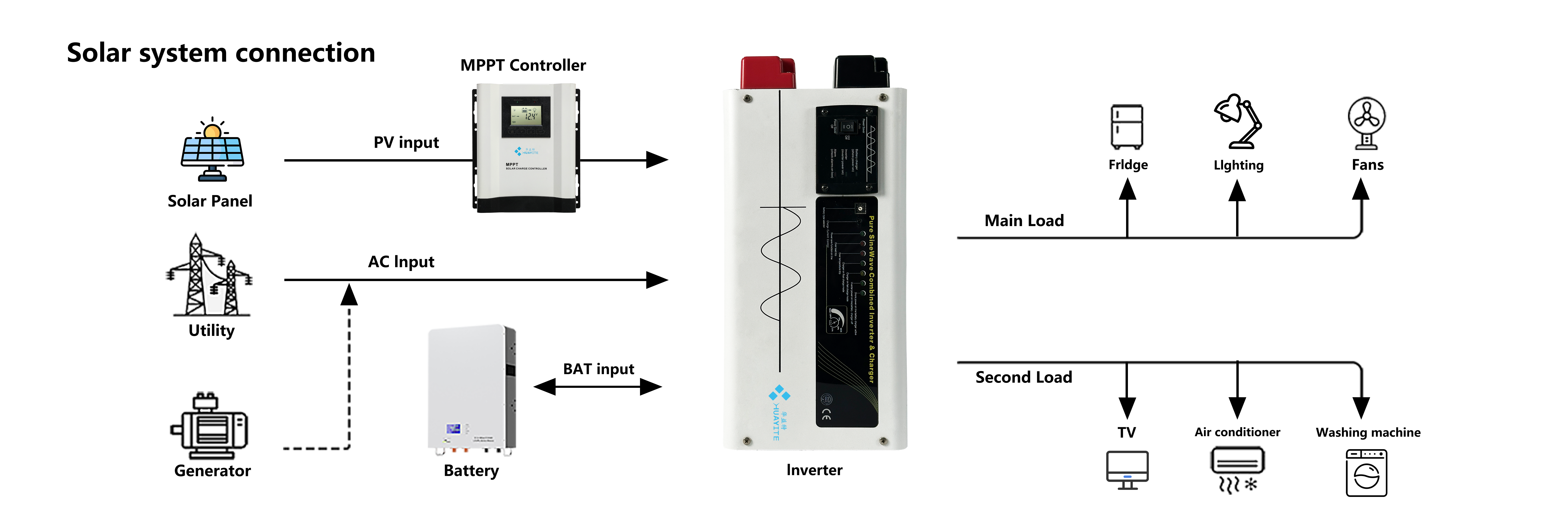
The HC Series is a power frequency inverter charger built on a low-frequency transformer. That one decision explains the rest of the unit: a substantial transformer between the battery and the AC side, a chassis built to carry its weight, and an output that keeps its shape when a pump or a compressor starts. It is also more than an inverter. The unit takes a solar array, a grid connection and a standby diesel generator onto one power path and decides which source the load sees, with the changeover happening on its own. That breadth is what distributors and integrators comparing solar power inverter manufacturers are usually after: one box covering the whole site instead of three that have to be wired to agree with each other. On the wall it is a rectangular metal housing with a front control panel and keypad, a row of LED status indicators, and a rear terminal block with red and black battery posts next to a resettable protection breaker. The terminal layout does not change with size, so a technician moving between a 12V inverter charger and a 48 V model meets the same arrangement. The power path has four connections and one controller. On the DC side, the rear terminal block takes a battery bank at 12/24/48VDC, red to positive and black to negative. On the AC side, one input takes the grid or a diesel generator and one output feeds the protected distribution board. The charger sits between the AC input and the DC side; the inverter sits between the DC side and the AC output. A solar array joins the same DC bus through its own charge controller, so the battery is the meeting point for everything: array, charger, inverter and load. This is the arrangement solar power inverter manufacturers are usually asked to support in regions where the grid is unreliable and a generator is already on site — three sources, one battery, one set of loads. In normal operation the hybrid inverter sits in bypass, passing grid or generator power to the load while the charger maintains the bank. When the input disappears or drifts outside the safe window, the inverter takes the load from the battery. When the input returns, the charger resumes and the load transfers back, with no manual reset and nobody in the room. The control path runs alongside the power path: the rear remote control port and the communication interfaces are part of the same layout rather than an addition made later. Single-line drawings and the current datasheet are available from your sales contact for tender packs and site files.
The series runs on one transformer platform in seven ratings: 1000W, 1500W, 2000W, 3000W, 4000W, 5000W and 6000W. Because the platform is shared, surge behaviour scales predictably — peak output is three times the continuous rating, from 3000W on the smallest unit to 18000W on the largest — and motor starting capability climbs in step, from 1HP on the 1000W model to 6HP on the 6000W model. As solar power inverter manufacturers, we build all seven on the same chassis family, so the terminal layout and the control panel are familiar from the smallest unit to the largest.
Sizing a hybrid inverter is a matter of the load, not the label. A 2000W model starts a 2HP motor and carries a small workshop; 4000W and above is where borehole pumps, compressors and multi-motor panels become realistic. Battery voltage narrows the field further: a 48v inverter charger is the usual choice once the load moves into the multi-kilowatt band, because the higher DC voltage keeps current and cable size manageable, while 24 V systems stay practical for smaller loads and short cable runs.
When you compare pure sine wave power inverter suppliers on a range like this, the useful questions are what the surge figure actually starts, how a technician reaches the control board, and whether the same platform will still be available for the next order. Send us the load list and the battery bank you intend to use, and we will confirm which rating covers it.
The charger is the part of this unit that decides how long a battery bank lasts, and a long outage is where that shows. What follows describes what happens to the bank while the grid is down, which settings a site can change to protect it, and what to check before the next outage.
Through a long outage
The charger draws from whatever source is connected to the AC input — the grid, or a standby diesel generator. While that source is present, the site load runs through bypass and the charger works on the bank at the same time, so the two do not compete for the unit. When the source disappears, the inverter takes the load from the battery and the bank starts to fall; a solar array on its own charge controller keeps pushing current into the same DC bus in daylight, which slows the fall but rarely stops it. When the generator comes on, the charger picks the bank up again while the load stays on bypass, so an outage covered by generator running ends with a charged bank rather than a flat one. As charging finishes, current tapers away rather than being held at a high rate to the end, which is the part of the cycle that protects plate life on a lead-acid bank.
Settings that decide bank life
Two decisions belong to the installer, and both are made with the DIP switches before commissioning. The battery undervoltage threshold sets how far the inverter will discharge the bank before it stops: raise it and you protect cycle life at the cost of runtime, lower it and the site runs longer on a deeper discharge. The AC input window decides when the unit treats the incoming supply as unusable and transfers the load to inverter mode, which matters on a generator whose voltage wanders through the day. On a site with repeated multi-hour outages, these two settings do more for battery life than any other adjustment on the unit.
What to send us
Charging current is set by the model, so the bank has to suit the unit rather than the other way round. Give us the amp-hour rating, the chemistry — flooded, AGM, gel or a lithium pack — and roughly how long an outage lasts and how often the generator runs, and we will check the rating you have chosen against it and confirm the settings that go with it. After commissioning, watch the bank across the first few outages: it should return to float between them. If it never does, the bank is oversized for the charging it receives or the outages are longer than the charger can recover from, and that is worth raising with us before the batteries pay for it.
| Topology | Power frequency inverter with a low-frequency transformer |
| Nominal battery system voltage | 12/24/48VDC and 24/48VDC depending on model |
| Waveform | Pure sine wave (grid or generator) |
| Output voltage | 100/110/120/220/230/240VAC |
| Output frequency | 50Hz / 60Hz ±0.3Hz |
| Inverter efficiency (peak) | > 88% |
| Line mode efficiency | > 95% |
| Power factor | 1.0 |
| Typical transfer time | 10ms(max) |
| AC input voltage | 100/110/120/220/230/240VAC |
| Frequency range | 50Hz / 60Hz(Auto sensing) 40~80Hz |
| Inverter dimensions (WHD) | 360*185*180 mm / 420*185*180 mm / 597*195*190 mm |
| Package dimensions (WHD) | 520*315*305 mm / 580*315*305 mm / 760*325*310 mm |
| Inverter weight | 13.5kgs |
| Lead time, standard models | 3-7 days |
| Lead time, customized orders | 15-30 days |
| Warranty | 2-year warranty |
| Configuration options | power rating 1 kW to 6 kW, output voltage 100/110/120/220/230/240VAC, 50Hz or 60Hz |
| Packed weight | 15.5 kg / 15.5 kg / 19 kg / 23.5 kg / 29.5 kg / 31.5 kg / 32.5 kg |
| Order quantity | confirmed with your sales contact for each project |
| Documentation | datasheet, user manual and system diagram, available from your sales contact |

Choosing the right unit for a site starts with a conversation, not a catalogue number. Share your load profile, battery voltage and backup requirement, and our engineers will help you match a model from our full range and confirm the accessories that go with it. The same Shenzhen-based team, with in-house R&D and more than 20 years in the industry behind them, stays with you after delivery: wiring and commissioning guidance, fault diagnosis, and spare-part support for units already in service. For private-label projects, they also handle artwork and specification approvals before production.
- Documentation follows the clause list, not the product name. A safety or EMC report only means something next to the clauses it covers, so send the standard your market or utility names as a numbered clause list. The answer comes back in the same shape: the test items we hold results for on this platform, and the items we do not. - Safety items buyers ask for first. Electric strength, insulation resistance, protective earthing and temperature rise are the usual headline checks, alongside verification of the overvoltage, undervoltage, overload and short-circuit protections built into the unit. Once the standard is known we confirm which of those items appear in the reports available for this model. - EMC is a separate document. Conducted emissions, radiated emissions and immunity are tested under the EMC standard, not the safety one, and holding one does not imply the other. If your market requires both, ask for both by name. - Where this unit stops. It does not export power to a utility network, so anti-islanding and grid-code approvals belong to grid-tied equipment and should not be assumed here. If a project specification includes them, raise it at enquiry stage and we will say plainly what is and is not available before you commit to a bid. - Two-year warranty, with terms written into the order. Every unit is covered for two years. Put the start date, the serial number range and the party handling the claim in your market into the purchase documents, so a distributor's customer and the factory are working from the same page when something goes wrong. - Transport damage and in-service faults. Inspect cartons at delivery and note any damage on the carrier's paperwork before signing — that record is what makes a transit claim stand. For a unit that fails in service, send the model, the rating printed on the label, a photograph of that label and a short description of the fault, and diagnosis starts from there. - Spares that keep a site operational. Agree with us which parts you hold for the ratings you stock and bring them in with the inverters rather than after the first failure. A distributor carrying two or three ratings needs a different spare set from a project buyer running one model across a rollout, so ask for the list that matches your case.
Nominal battery system voltage is 12/24/48VDC on some models and 24/48VDC on others, so the same series covers a small 12 V installation and a 48v inverter charger bank. In practice the bank you already own usually decides the model rather than the other way round; if you are building from scratch, tell us the load and the autonomy you need and we will work back to a voltage and a rating.
Yes, inside the series: power ratings from 1 kW to 6 kW, output voltages across 100 to 240 VAC, and 50Hz or 60Hz. As a power inverter manufacturer we set these at production rather than adding them afterwards, so the unit arrives configured for the market it is going into. Confirm the exact configuration on your order and we will build to it.
Yes. The AC input accepts grid or generator supply and senses frequency automatically, so a generator that is not perfectly stable is still a usable source. While the unit is inverting, the load sees a pure sine wave inverter waveform regardless of how rough the generator's own output is. In bypass the load follows the generator directly, so if the generator is very poor quality it is worth telling us before you rely on passthrough.
The series is built for renewable energy systems, utilities, marine and RV use and emergency backup, and we can send the test documentation and certificates we hold for the platform. Documentation requirements vary by market, and solar power inverter manufacturers are routinely asked for reports that only apply to grid-tied equipment, so tell us the standard the project is specified against and we will confirm what is available for this model before you quote it.
Charging runs in stages with automatic current regulation, so the final part of the charge is gentle rather than a fixed high rate held to the end. The charger keeps working whether the hybrid inverter is in bypass or inverting from the battery, which means the bank is being refilled whenever an AC source is present. Bank size and chemistry still matter — send us the amp-hour figure and we will confirm the charging setup.
A high-frequency unit is lighter and more compact for the same wattage; this one carries a low-frequency transformer, which is where the surge headroom and the galvanic isolation come from. When buyers compare pure sine wave power inverter suppliers, the decision usually turns on whether the site has motors and a generator, or only electronics and a stable grid.
There is nothing user-serviceable inside the enclosure. Routine attention is limited to keeping the side grille and fan clear of dust, checking that the battery terminals remain tight, and confirming the display still reads the expected output voltage and frequency. Anything beyond that belongs to authorised service personnel, and the battery must be disconnected before the cover comes off.
Smart Remote Management: Multi-protocol (RJ11/RJ45/RS232/RS485) for remote monitoring. 4-in-1 Integration: Seamless auto-switching between bypass/grid charging/inverter/UPS modes. Robust Performance: 3x rated power surge capacity handles demanding motorized/inductive loads. Adaptive Charging: 4-stage smart AC charging with auto-current adjustment maximizes battery longevity. Premium Power Quality: Pure sine wave output with galvanic isolation ensures device compatibility & safety. Dual Interface Visibility: LED status indicator + optional LCD remote display for real-time parameter tracking. Full-System Protection: Integrated safeguards against undervoltage/overvoltage/short-circuit/overload/overheat. Multi-Industry Application: Certified for renewable energy systems, utilities, marine/RV use & emergency backup. IoT-Ready Monitoring: PC software control + expandable WiFi/4G modules for real-time cloud-based app access. Hybrid Power Flexibility: Seamless integration with solar/grid/diesel generators for uninterrupted hybrid operations. Superior Efficiency: 3-5% higher efficiency & 30-50% lower self-consumption vs common power frequency systems. Customizable Configurations: DIP-switch adjustable battery protection thresholds/input ranges/power priorities/ECO mode. Key Value Propositions for Distributors: 


